CNC3020T: switch-mode power supply conversion
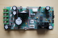
Tags:As I wrote earlier, the 3020T CNC mill has great mechanics, but somewhat flaky electronics. In this note, I will explain how to get rid of the transformer and use more efficient, more reliable, lighter, dual-voltage switch-mode power supplies.
Tools
- electric drill
- generic
- d=3mm drill bit
- generic
- clamper/cutter
- generic
- black permanent marker
- generic
Components
110V-220V/24V 2A power supply- LIHUA-48W
Update 2015-09-23: I’ve received reports that all three motors draw ~2.4A at full speed, so it is advisable to use a power supply rated for at least 3A.
- 110V-220V/48V 5A power supply
- Meanwell S-240-48
Materials
- M3x6 screw ×7
- generic
- M4x12 screw x1
- generic
- 0.5mm² multistranded hookup wire ×5m
- generic
- 3.7mm U-type terminal (0.25-1.65mm wire) ×6
- generic
- 4.3mm U-type terminal (0.25-1.65mm wire) ×10
- generic
Assembly
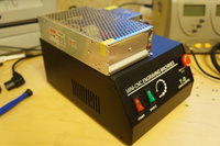
Keep in mind that due to space constraints, the switchmode power supplies are installed on the control box, not inside it.
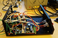
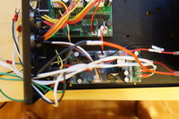
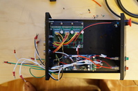
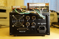
There are two main areas in the control block that should be rewired: the spindle board (which routes power to the stepper/logic board) and the mains input.
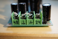
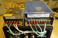
For the spindle control board, it’s only necessary to add some extension wires. It’s quite convenient that the board has screw terminals; it allows to avoid any soldering. The stepper board mates with the 3.5mm wire clamps. The wires need to be about 30cm long and the other end should have a 4.5mm wire clamp on it, as that’s what fits the power supply terminals.
For the mains input, solder two wires to the neutral terminal on the socket, two wires to the live terminal on the on/off switch, and attach two more wires with 4.5mm wire clamps on both ends to the screw near the power socket to which the grounding terminal of the socket is connected.
Mark the wires in a way that would prevent accidental mixups. I used shrink tubing and a permanent marker.
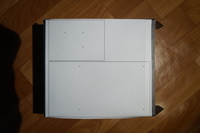
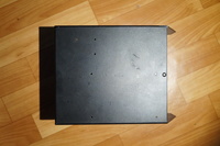
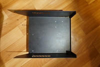
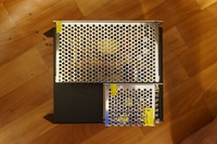
Now we need to attach the power supplies to the top of the box. For this, I have used the mounting holes present on the bottom of the supplies. I drilled the control box using a printed A4 template (attached with duct tape) for guiding the drill.
Before drilling, make sure that your printer or software did not distort the template; try to line up the circles on the template with the mounting holes on the power supplies.
Note that the supplies have a rather poor way of isolating the PCB from the conductive aluminium case; it’s just a thin, flexible plastic sheet. As such, make sure that the screws do not penetrate too far into the power supply case. I couldn’t easily find appropriately short screws, so I used bolt cutter.
After attaching the supplies, it is a simple matter of connecting the corresponding terminals. Take care to not accidentally swap live and neutral lines; nothing good would come out of it. Check continuity of all the connections, especially grounding; if it is broken, the control box will shock you on touch.
Results
I have used the mill for several months after this modification. It works very smoothly on a wide range of loads. The supplies do not get hot even after prolonged continuous machining.
