G38: Probing workpieces in LinuxCNC
Tags:Touching off to the workpiece by hand is tedious and error-prone. Fortunately, LinuxCNC has the very convenient G38 code family, which allows to automate this process. In this note I demonstrate how G38 can be used, using squaring aluminium stock as an example.
Hardware
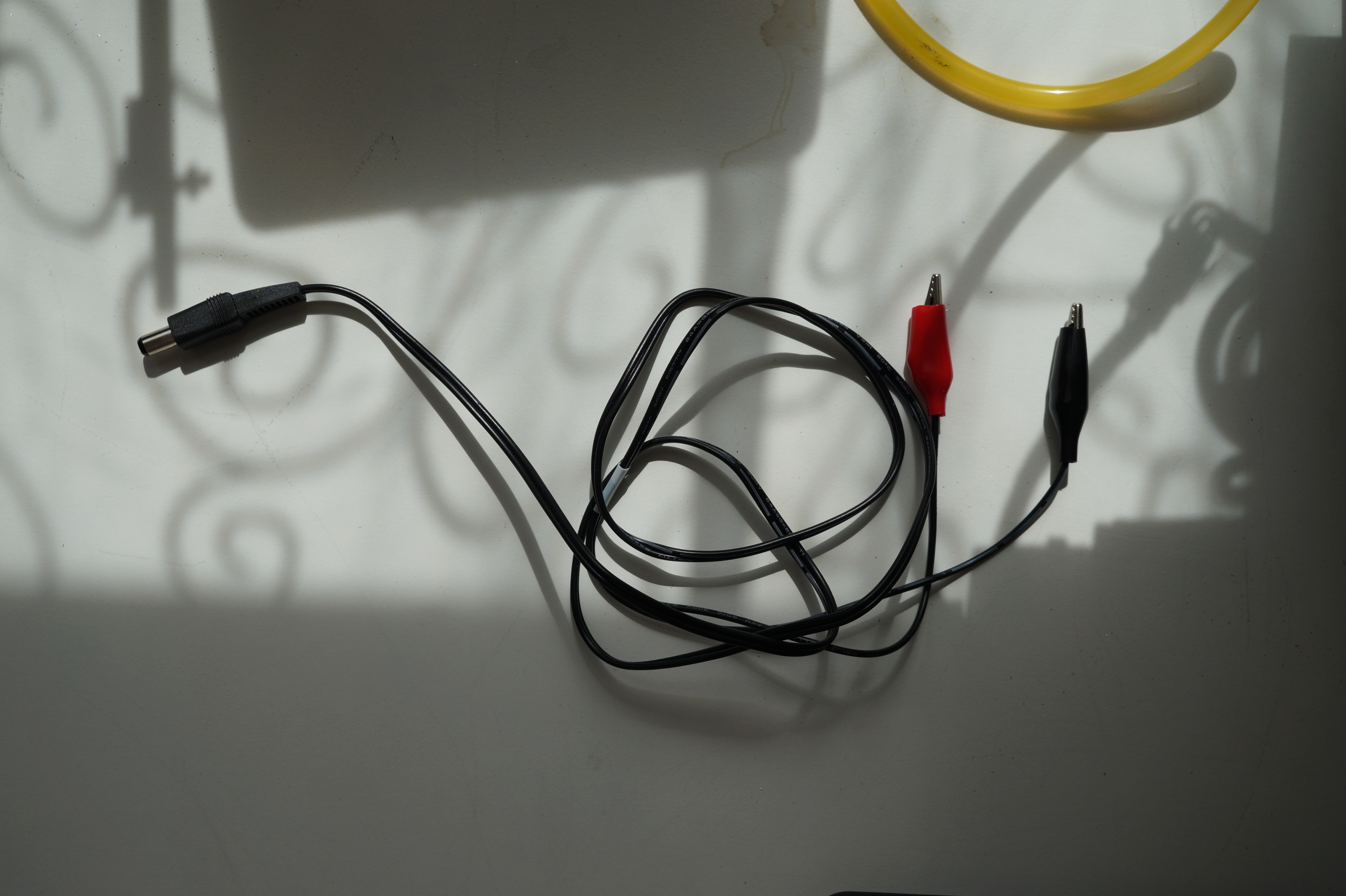
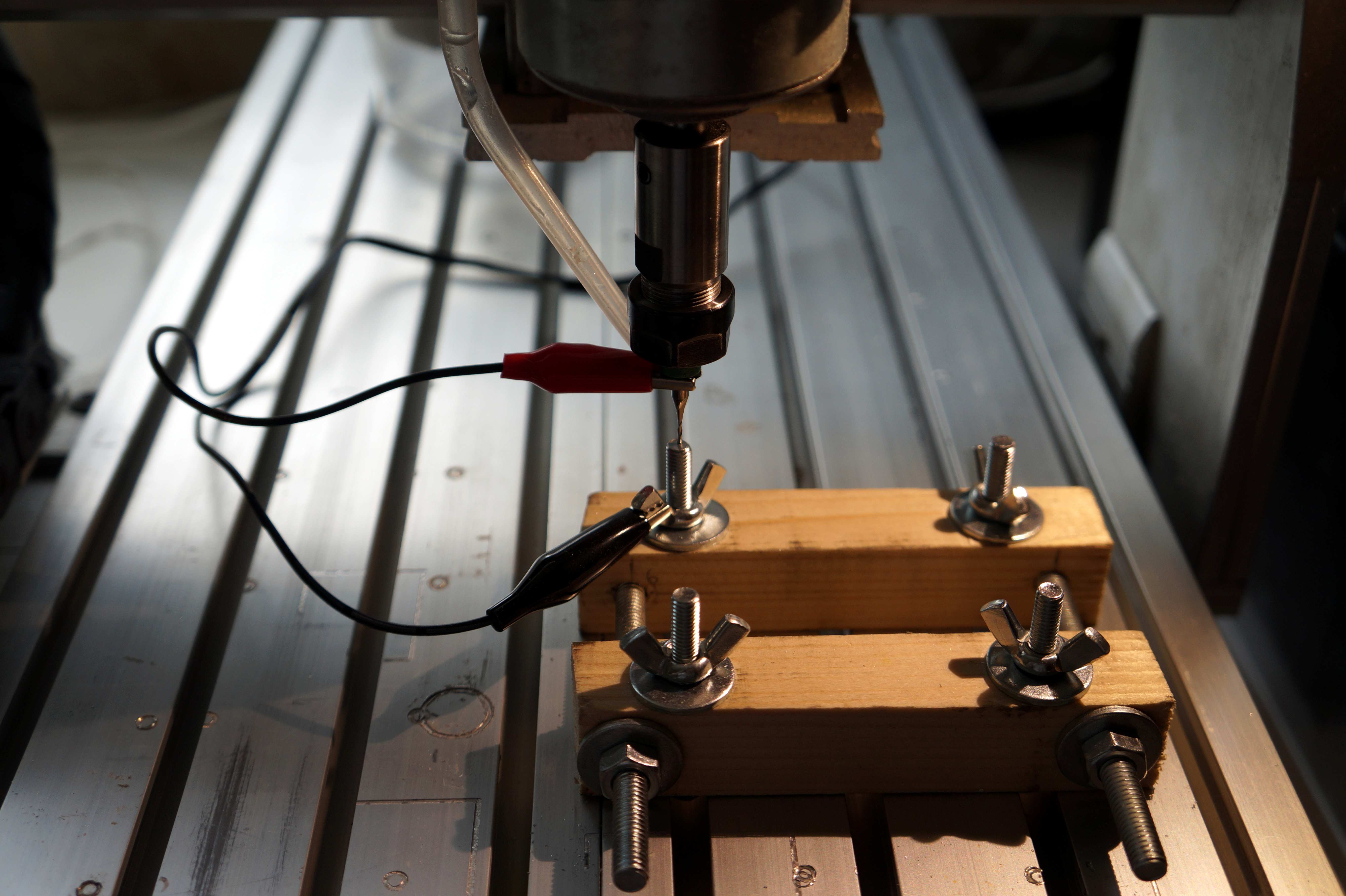
In our case, the probe itself is very simple–it’s just a pair of alligator clips. One of the clips is clamped over the tool, the other is somehow connected to the workpiece. Depending on the CNC controller, the way of connecting the probe can vary, but in case of my CNC3020T machine, it’s just a 2.1x5.5 DC barrel jack. The controller outputs bias voltage and reports a short circuit to LinuxCNC.
While using the tool you’ll be machining the workpiece with can be simpler–less tool changing, no need to use G43 tool length compensation–an incorrect probe setup or flaky contact can result in a broken tool. It may make sense to use the butt of a (broken) tool as a probe.
LinuxCNC setup
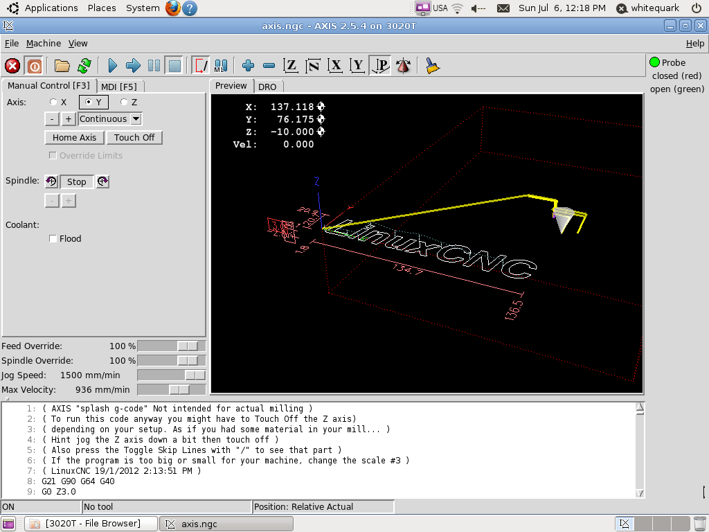
In addition to configuring the probe input in the machine settings, I found it helpful to have a HalUI widget indicating the probe status. This way, it’s easy to verify if there’s a good contact between the probe and the workpiece.
Merge the following with your LinuxCNC config (at ~/linuxcnc/machinename/):
1
2
3
4
5

[DISPLAY]
PYVCP = custompanel.xml

[HAL]
POSTGUI_HALFILE = custom_postgui.hal
1

net probe-in => pyvcp.probe-in
1
2
3
4
5
6
7
8
9
10
11
12
13
14
15
16
17
18
19
20
21

<pyvcp>
  <vbox>
    <hbox>
      <led>
        <halpin>"probe-in"</halpin>
        <size>15</size>
        <on_color>"red"</on_color>
        <off_color>"green"</off_color>
      </led>
      <label>
        <text>"Probe"</text>
      </label>
    </hbox>
    <label>
      <text>"closed (red)"</text>
    </label>
    <label>
      <text>"open (green)"</text>
    </label>
  </vbox>
</pyvcp>
Example: probing a cube
The following G-code program probes the dimensions of a cube and sets the coordinate system centered at the face. See the comments in the file for operating instructions.
1
2
3
4
5
6
7
8
9
10
11
12
13
14
15
16
17
18
19
20
21
22
23
24
25
26
27
28
29
30
31
32
33
34
35
36
37
38
39
40
41
42
43
44
45
46
47
48
49
50
51
52
53
54
55
56
57
58
59
60
61
62
63
64
65
66
67
68
69
70
71
72
73
74
75
76
77
78
79
80
81
82
83
84
85
86
87
88
89
90
91
92
93
94
95
96
97
98
99
100
101
102
103
104
105
106
107
108
109
110
111
112
113
114
115
116
117
118

; This G-code program probes a cube and sets the current coordinate
; system so that it is centered at the face and Z is zero at highest point.
; The variable #5190 is set to edge length, and #5191 is set to the Z difference
; between highest and lowest point.
;
; This script should be invoked twice.
; At first invocation, tool should be positioned by XY within #<_delta> of
; nearer left corner. The corner will be found. At second invocation, tool
; should be positioned by XYZ within 5mm of farther right corner above surface.
; The corner will be found, and surface will be probed at five points.
;
; G-code wise, current tool length and diameter are used, and current
; coordinate system is adjusted.
;
; Reset #5199 to 0 to re-run first step.

G21 G91 G17 ; Metric, Incremental, XY plane
G43         ; Length compensation on
F50         ; Probing feedrate

#<_delta> = 8.0 ; [mm]

; O<max> call [N] [V1] ... computes maximum of N>=1 values Vn and
; returns it in #31.
O<max> sub
  #31 = #2
  O10 if [ #1 GT 1 ]
    O20 if [ #[#1+1] GT #31 ]
      #31 = #[#1+1]
    O20 endif
    #1 = [ #1 - 1 ]
  O10 endif
O<max> endsub

; O<min> call [N] [V1] ... computes minimum of N>=1 values Vn and
; returns it in #31.
O<min> sub
  #31 = #2
  O10 if [ #1 GT 1 ]
    O20 if [ #[#1+1] LT #31 ]
      #31 = #[#1+1]
    O20 endif
    #1 = [ #1 - 1 ]
  O10 endif
O<min> endsub

O100 if [ #5199 EQ 0 ]
  ; first invocation

  ; probe X and return
  G0    Y#<_delta>
  G38.2 X#<_delta>
  G10 L20 P#5220 X[-#5410/2]
  G0    X[-#<_delta>/2]
  G0    Y-#<_delta>

  ; probe Y and return
  G0    X#<_delta>
  G38.2 Y#<_delta>
  G10 L20 P#5220 Y[-#5410/2]
  G0    Y[-#<_delta>/2]
  G0    X-#<_delta>

  ; results
  #5199 = 1
  (msg,Position next to far right corner and restart)
O100 else
  ; second invocation

  ; probe X and return
  G0    Y-#<_delta>
  G38.2 X-#<_delta>
  #<xsize> = [#5420-#5410/2] (debug,X size: #<xsize>)
  G10 L20 P#5220 X[#<xsize>/2 + #5410/2]
  G0    X[#<_delta>/2]
  G0    Y#<_delta>

  ; probe Y and return
  G0    X-#<_delta>
  G38.2 Y-#<_delta>
  #<ysize> = [#5421-#5410/2] (debug,Y size: #<ysize>)
  G10 L20 P#5220 Y[#<ysize>/2 + #5410/2]
  G0    Y[#<_delta>/2]
  G0    X#<_delta>

  ; record size
  #5190 = [ [#<xsize> + #<ysize>] / 2 ]

  ; probe surface
  O<120> sub
    G90 G0 X#1 Y#2
    G91 G38.2 Z-#<_delta>
    #[#3] = #5063
    G0 Z[#<_delta> / 2]
  O<120> endsub

  G0 Z#<_delta>
  O<120> call [-[#5190/2-#<_delta>/2]] [-[#5190/2-#<_delta>/2]] [100]
  O<120> call [-[#5190/2-#<_delta>/2]] [+[#5190/2-#<_delta>/2]] [101]
  O<120> call [+[#5190/2-#<_delta>/2]] [+[#5190/2-#<_delta>/2]] [102]
  O<120> call [+[#5190/2-#<_delta>/2]] [-[#5190/2-#<_delta>/2]] [103]
  O<120> call [0]                     [0]                     [104]

  ; calculate
  O<max> call [5] [#100] [#101] [#102] [#103] [#104]
  G10 L20 P#5220 Z[#104 - #31 + #<_delta>/2]
  #<max> = #31

  O<min> call [5] [#100] [#101] [#102] [#103] [#104]
  #5191 = [ abs[#<max> - #31] ]
  (debug,Probe OK. Cube L=#5190mm, dZ=#5191mm)

  ; finalize
  #5199 = 0
  G90
O100 endif

M2
Example: squaring a cube
The following G-code program mills flat the face of a cube. It uses the results of probe-cube.ngc to determine the dimensions.
1
2
3
4
5
6
7
8
9
10
11
12
13
14
15
16
17
18
19
20
21
22
23
24
25
26
27
28
29
30
31
32
33
34
35
36
37
38
39
40
41
42
43
44
45
46
47
48

G21 G90 G17 ; Metric, Absolute, XY plane
T01 G43 M06 ; 1mm cylindrical

; 6061 Al
S8000
#<_feed>   = 200
#<_plunge> = 40

; length of edge
#<_size>   = [ #5190 + 2 ] ; [mm] derived from probe-cube.ngc
#<_depth>  = #5191         ; [mm]
#<_step>   = 0.2           ; [mm]

; initial positioning
G0 Z1
G0 X0 Y0

M03 ; spindle CW

; mill layers of #<_step> height
#<pos_v> = 0
O100 while [ #<pos_v> LT #<_depth> ]
  #<pos_v> = [ #<pos_v> + #<_step> ]
  O110 if [ #<pos_v> GT #<_depth> ]
    #<pos_v> = #<_depth>
  O110 endif
  F#<_plunge> G1 Z-#<pos_v>

  ; mill face in steps of tool radius
  ; the first circle has 100% TEA, hence it uses
  ; lower feedrate
  #<pos_h> = [ #5410 * 0.6 ]
  F#<_plunge> G1 X-#<pos_h>
  O120 while [ #<pos_h> LE #<_size>/2*sqrt[2] ]
    G2 I#<pos_h> ; conventional milling
    #<pos_h> = [ #<pos_h> + #5410 * 0.6 ]
    F#<_plunge>  G1 X-#<pos_h>
    F#<_feed>
  O120 endwhile

  G0 Z0
  G0 X0 Y0
O100 endwhile

; final positioning
G0 Z10

M02