A fixture attachment system for CNC3020T
Tags:I found it convenient to have a table with a grid of nuts for attaching the workpieces, that could double as victim material. In this note I describe how to make such a table out of HDPE.
Introduction
My first prototype used a plywood board, however, that doesn’t work well with water as coolant; also, plywood tends to deform in unexpected and non-uniform ways. HDPE is cheap, easily machined, works well as victim material, and resists deformation well.
This note describes a table with uniform 8x7 nut array, spaced 30mm between nuts, accepting M4 screws; there is at least 3mm of victim material at any point (5.2mm over nuts, 3mm over mounting screws).
All G-code is parametric (it thus requires LinuxCNC) and can be easily customized if other parameters are needed.
Tools
- jig saw
- DEXTER IC400JS
- jig saw blade
- Bosch T301CD
- drill press
- PRACTYL 500W with 16mm collet
- d=6mm wood drill bit
- generic
- CNC mill
- CNC3020T
- d=3.175mm cylindrical endmill
- generic
- d=1.5mm l=7.5mm cylindrical endmill
- generic
Materials
- HDPE sheet, 300x300x12.7mm
- generic
- {M6x40 screw, M6 wing-nut, M6 washer} ×4
- generic
- {M6x12 bolt, M6 nut} ×6
- generic
- M4 nut ×42
- generic
Process
Sheet was cut to fit CNC3020T’s table of 300x200mm using a jig saw.

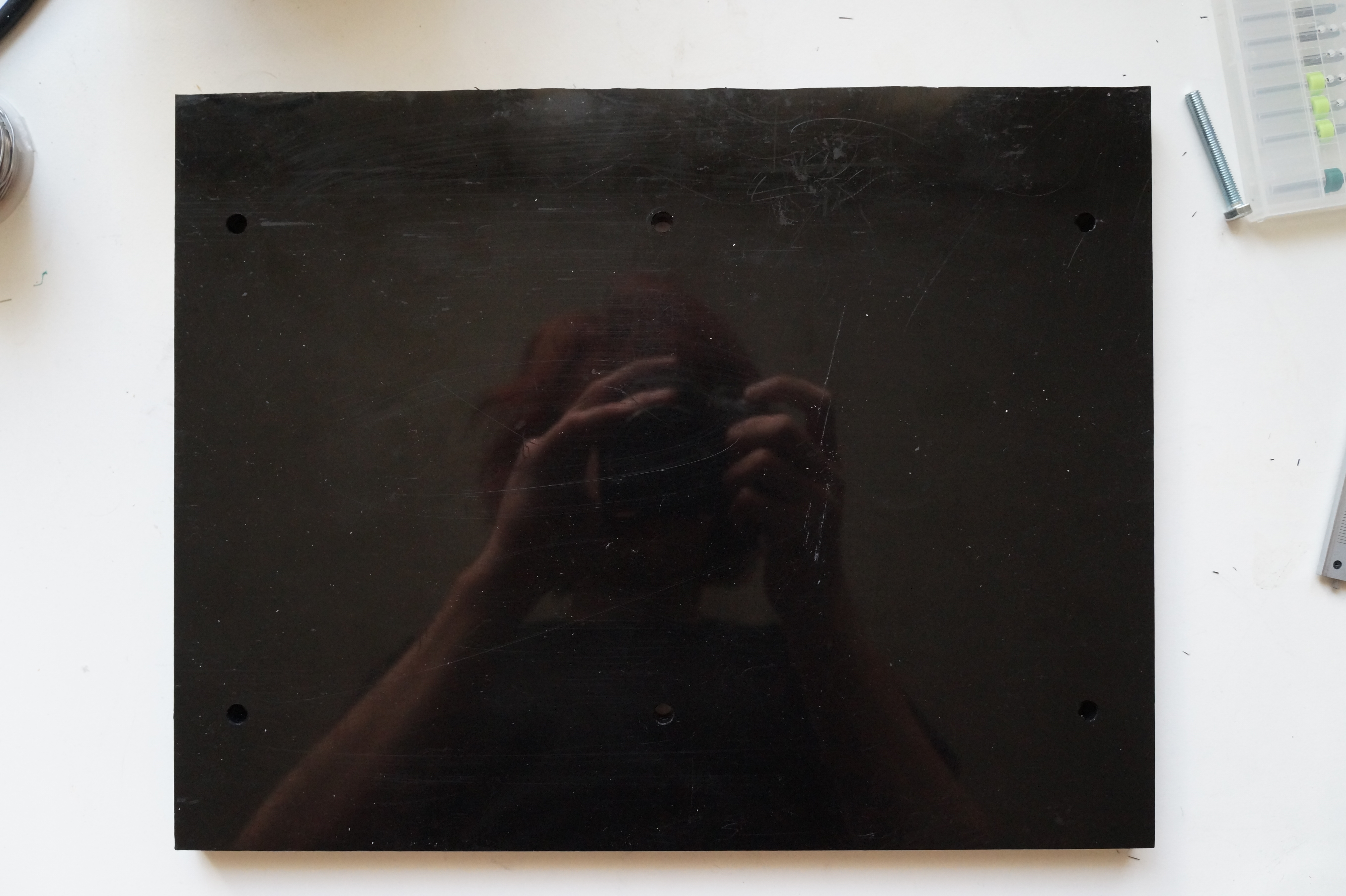
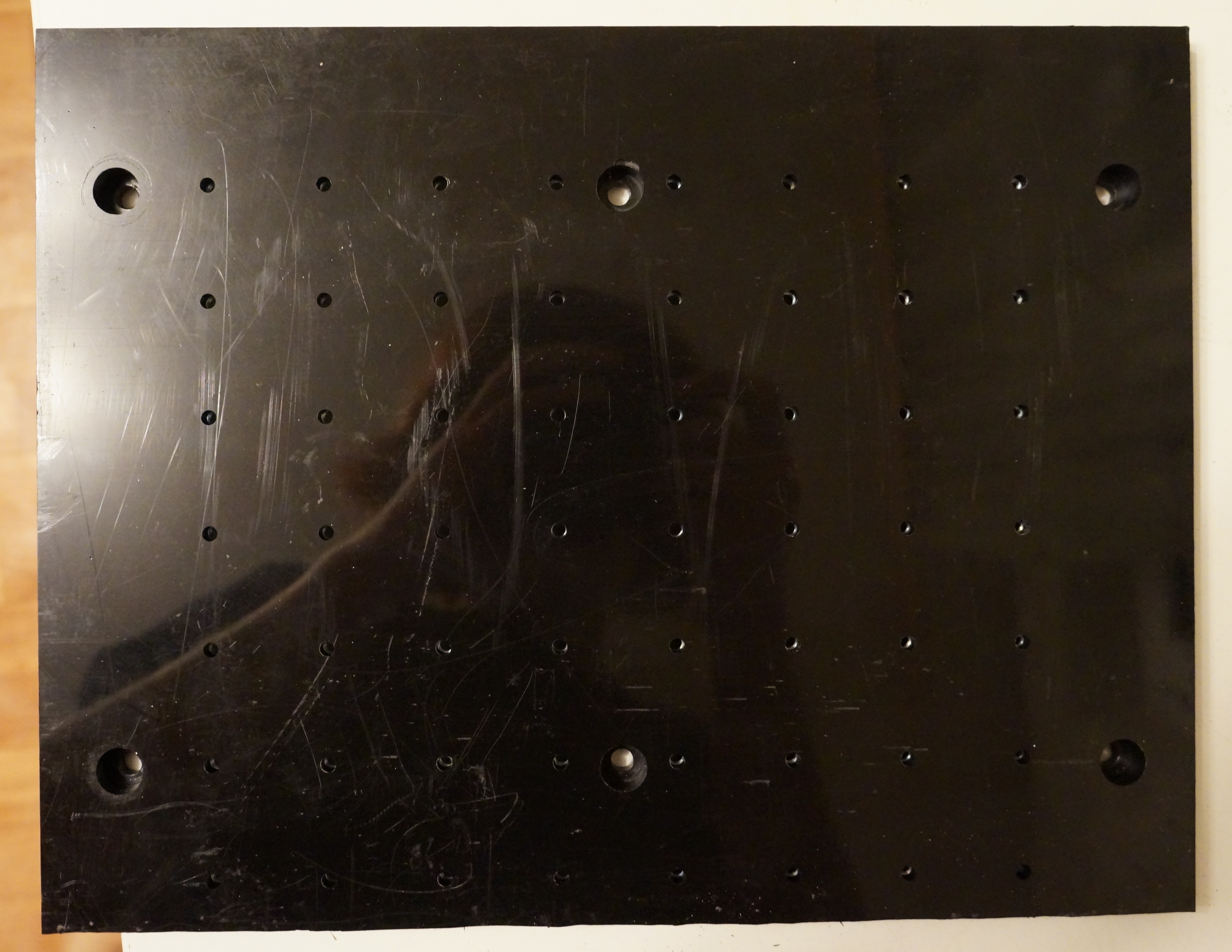
Mounting holes
Sheet was marked for drilling on a drill press using d=1.5mm endmill. Sheet wasn’t drilled on the mill itself to avoid crashing the endmill into the table.
Marking was done using the following G-code script. Origin corresponds to the top of sheet, center of nearest leftmost mounting hole.
1
2
3
4
5
6
7
8
9
10
11

S2500
M3
G0  Z6
G98
G81 X0   Y0   R1 Z-2 F300
    X0   Y130
    X0   Y260
    X150 Y0
    X150 Y130
    X150 Y260
M2
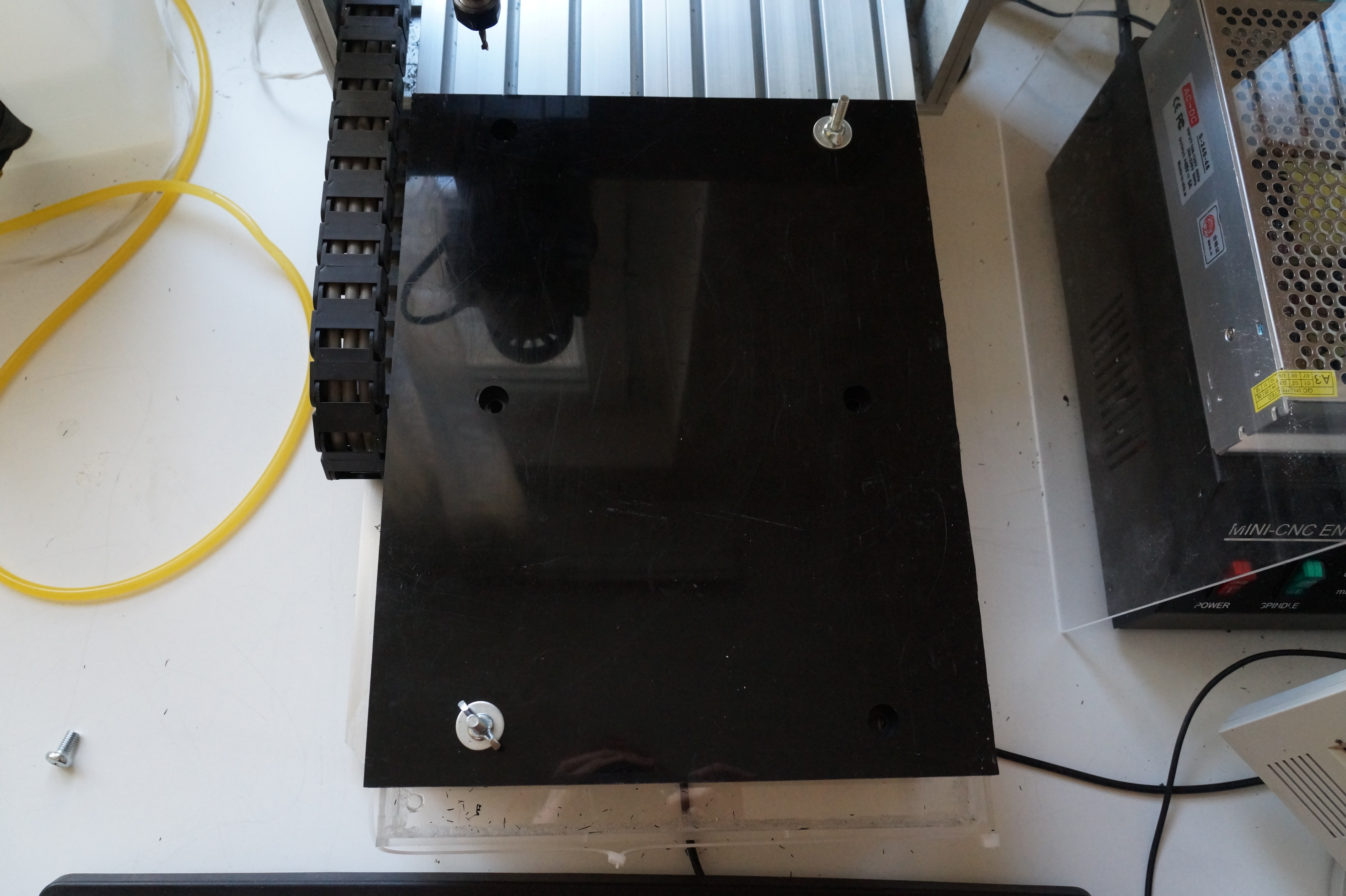
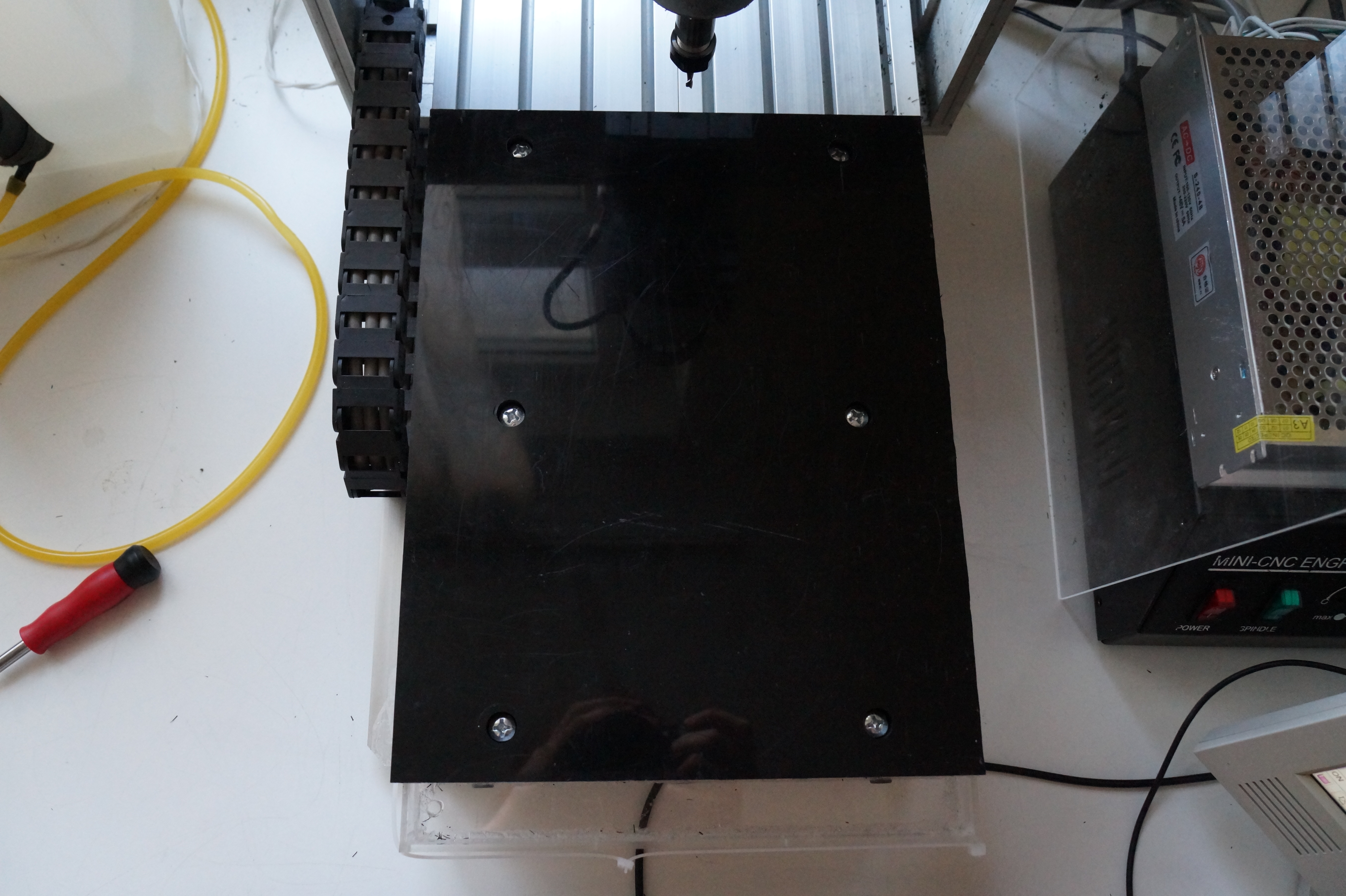
After drilling, pockets for screw heads were milled using d=3.175mm endmill. Initially, commands for milling first and last pocket were commented out and the sheet was attached using a M6x40 bolt in the T-slot, washer and a wingnut. After that, the sheet was reattached properly, i.e. using M6x12 screw and a nut in the T-slot, and the remaining pockets were milled.
1
2
3
4
5
6
7
8
9
10
11
12
13
14
15
16
17
18
19
20
21
22
23
24
25
26
27
28
29
30
31
32
33
34
35
36
37
38
39
40
41
42
43
44
45
46
47
48
49
50
51
52
53
54
55
56
57
58
59
60
61
62
63
64
65
66
67
68
69
70
71
72
73
74
75
76
77
78
79
80
81
82
83
84
85
86
87
88
89
90
91
92
93

; === HELICAL MILLING ===

; Helix-mill a hole.
; Assumes metric, XY plane, feedrate, and tool compensation are set.
O<helix_mill> sub
  #<xcenter> = #1 ; [mm] X center
  #<ycenter> = #2 ; [mm] Y center
  #<radius>  = #3 ; [mm] Hole radius
  #<zstart>  = #4 ; [mm] Z start position
  #<zend>    = #5 ; [mm] Z end position

  G0 X[ #<xcenter> - #<radius> ] Y#<ycenter>

  G0 Z#<zstart>
  #<znow> = #<zstart>

  ; Mill out body with several full helical turns
  O100 while [ #<znow> GT [ #<zend> + #<_zstep> ] ]

    #<znow> = [ #<znow> - #<_zstep> ]
    G2 I#<radius> J0 Z#<znow>

  O100 endwhile

  G2 I#<radius> J0 Z#<zend>

  ; Flat out the bottom
  G2 I#<radius> J0

O<helix_mill> endsub

; === SCREW/NUT POCKETING ===

; Mill a pocket for a screw head.
; Assumes metric, XY plane, feedrate, and tool diameter are set.
O<screw_head_pocket> sub

  #<xcenter>     = #1 ; [mm] X center
  #<ycenter>     = #2 ; [mm] Y center
  #<head_radius> = #3 ; [mm] Screw head thickness
  #<head_depth>  = #4 ; [mm] Screw head depth

  ; Initial position
  G0 X#<xcenter> Y#<ycenter>

  ; Cutter compensation to the right.
  G42

  ; Make a pocket for screw head.
  #<rnow> = #<head_radius>
  O100 while [ #<rnow> GT [ #5410 / 2 ] ]

    O<helix_mill> call [#<xcenter>] [#<ycenter>] [#<rnow>] [0.] [-#<head_depth>]

    #<rnow> = [ #<rnow> - #5410 * 0.9 ] ; Subtract 90% tool diameter

    G0 Z0.0 ; Get tool up for another plunge

  O100 endwhile

  ; Cleanup.
  G40
  G0 Z#<_zsafe>

O<screw_head_pocket> endsub

; --- BEGIN CONFIGURATION ---

; Don't forget to set up tool table.

T2 M6 S2500 F300 ; 3.175mm cylindrical

#<_zsafe>       = 10.  ; [mm] Safe Z
#<_zstep>       = 3.   ; [mm] Z step

#<_thickness>   = 12.7 ; [mm] Sheet thickness
#<_head_radius> = 6.   ; [mm] Screw head radius
#<_head_depth>  = 8.   ; [mm] Screw head depth

; --- END CONFIGURATION ---

G21 G90 G17 ; Metric, Absolute, XY plane
M3

/O<screw_head_pocket> call [0]   [0]   [#<_head_radius>] [#<_head_depth>]
O<screw_head_pocket> call [0]   [130] [#<_head_radius>] [#<_head_depth>]
O<screw_head_pocket> call [0]   [260] [#<_head_radius>] [#<_head_depth>]
O<screw_head_pocket> call [150] [0]   [#<_head_radius>] [#<_head_depth>]
O<screw_head_pocket> call [150] [130] [#<_head_radius>] [#<_head_depth>]
/O<screw_head_pocket> call [150] [260] [#<_head_radius>] [#<_head_depth>]

G0 Z#<_zsafe>
M2
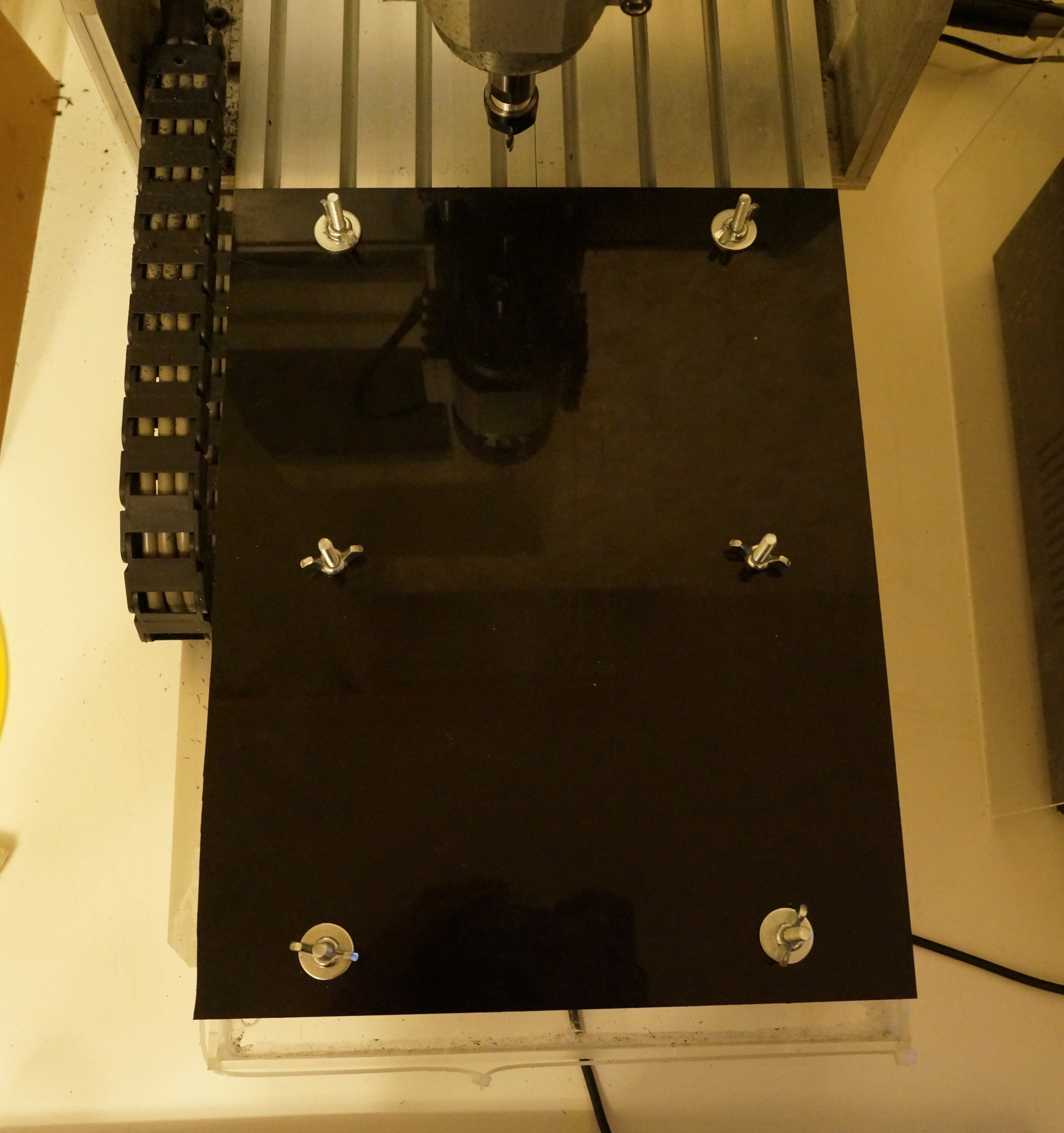
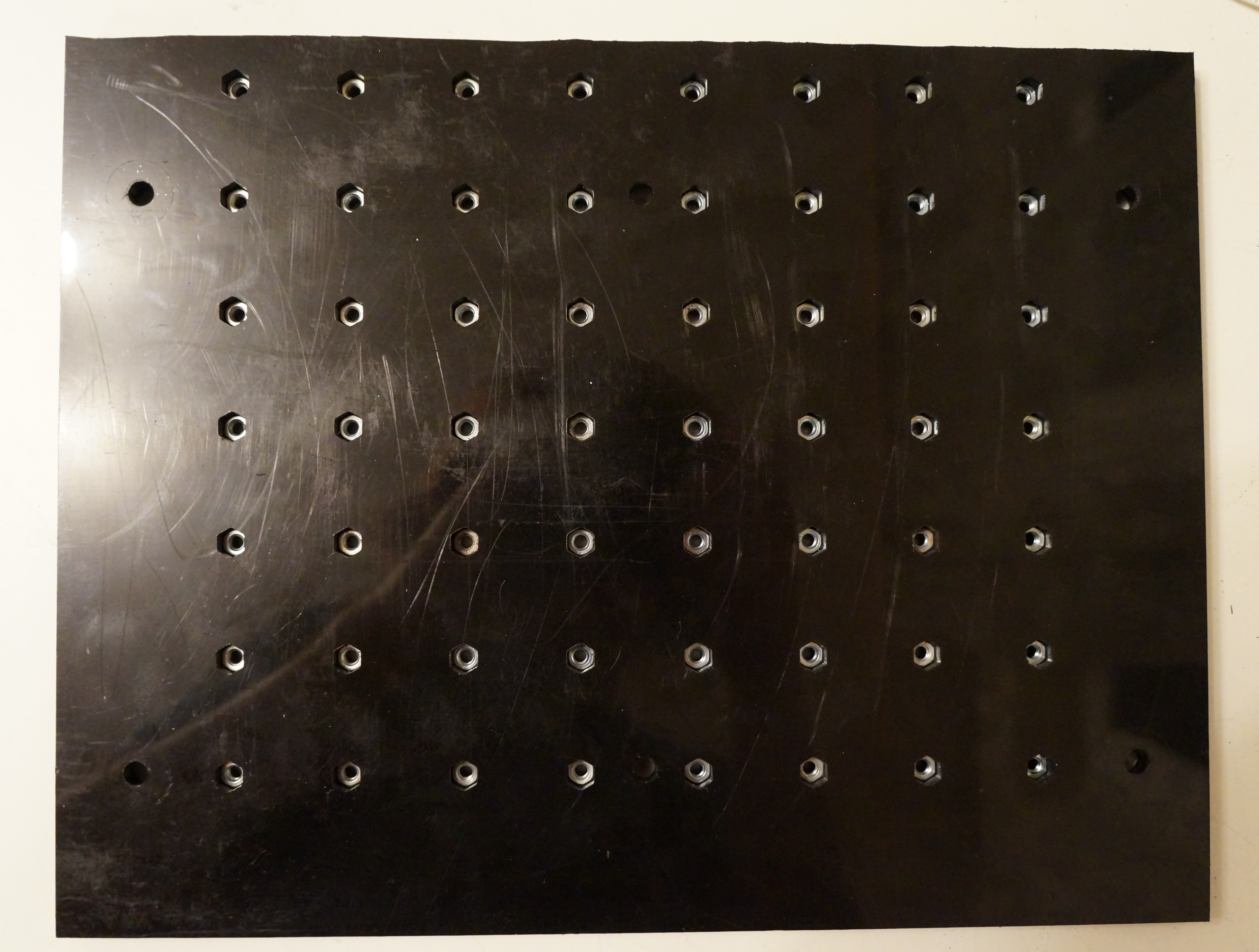
Nut slots
Sheet was fixed upside-down on the table. To avoid crashing the endmill into the table, a washer was placed between the table and the sheet, offsetting it by 2mm. In other words, a vertical slice through the mounting hole looks like: bolt head : T-slot : washer : sheet : washer : wing-nut.
The middle bolts should be removed despite being present on the picture. I discovered they would interfere with the spindle too late. I have replaced them with just a washer between table and sheet.
Pocketing was done using the following G-code script. The origin is at (13mm,45mm) from near left corner, owing to the asymmetry of the work area.
1
2
3
4
5
6
7
8
9
10
11
12
13
14
15
16
17
18
19
20
21
22
23
24
25
26
27
28
29
30
31
32
33
34
35
36
37
38
39
40
41
42
43
44
45
46
47
48
49
50
51
52
53
54
55
56
57
58
59
60
61
62
63
64
65
66
67
68
69
70
71
72
73
74
75
76
77
78
79
80
81
82
83
84
85
86
87
88
89
90
91
92
93
94
95
96
97
98
99
100
101
102
103
104
105
106
107
108
109
110
111
112
113
114
115
116
117
118
119
120
121
122
123
124
125
126
127
128
129
130
131
132
133
134
135
136
137
138
139
140
141
142
143
144
145
146
147
148
149
150
151
152
153
154
155
156
157
158
159
160
161
162
163
164
165
166
167
168
169
170
171
172
173
174
175
176
177
178
179
180
181
182
183
184
185
186
187
188
189
190
191
192
193
194
195
196
197
198

; === HELICAL MILLING ===

; Helix-mill a hole with pecking.
; Assumes metric, XY plane, feedrate, and tool compensation are set.
O<helix_mill> sub
  #<xcenter> = #1 ; [mm] X center
  #<ycenter> = #2 ; [mm] Y center
  #<radius>  = #3 ; [mm] Hole radius
  #<zstart>  = #4 ; [mm] Z start position
  #<zend>    = #5 ; [mm] Z end position

  G0 X[ #<xcenter> - #<radius> ] Y#<ycenter>

  G0 Z#<zstart>
  #<znow> = #<zstart>

  ; Mill out body with several full helical turns
  O100 while [ #<znow> GT [ #<zend> + #<_zstep> ] ]

    #<znow> = [ #<znow> - #<_zstep> ]
    G2 I#<radius> J0 Z#<znow>

    ; Peck
    G0 Z#<zstart>
    G0 Z#<znow>

  O100 endwhile

  G2 I#<radius> J0 Z#<zend>

  ; Peck
  G0 Z#<zstart>
  G0 Z#<zend>

  ; Flat out the bottom
  G2 I#<radius> J0

O<helix_mill> endsub

; Make one polygonal milling turn.
; Assumes metric, XY plane, feedrate, and tool compensation are set.
O<polygon_turn> sub
  #<xcenter> = #1 ; [mm] X center
  #<ycenter> = #2 ; [mm] Y center
  #<radius>  = #3 ; [mm] Hole radius
  #<zstart>  = #4 ; [mm] Z start position
  #<zend>    = #5 ; [mm] Z end position
  #<edges>   = #6 ;      Edge count

  #<zedgestep> = [ [ #<zend> - #<zstart> ] / #<edges> ]
  #<anglestep> = [ 360.0 / #<edges> ]

  #<znow>      = #<zstart>
  #<angle>     = 120.

  O100 repeat [ #<edges> ]

    #<znow>  = [ #<znow>  + #<zedgestep> ]
    G1 X[ #<xcenter> + cos[#<angle>] * #<radius> ] Y[ #<ycenter> + sin[#<angle>] * #<radius> ] Z#<znow>
    #<angle> = [ #<angle> - #<anglestep> ]

  O100 endrepeat

O<polygon_turn> endsub

; Helix-mill a polygonal hole.
; Assumes metric, XY plane, feedrate, and tool compensation are set.
O<polygon_mill> sub
  #<xcenter> = #1 ; [mm] X center
  #<ycenter> = #2 ; [mm] Y center
  #<radius>  = #3 ; [mm] Hole radius
  #<zstart>  = #4 ; [mm] Z start position
  #<zend>    = #5 ; [mm] Z end position
  #<edges>   = #6 ;      Edge count

  G0 X[ #<xcenter> - #<radius> ] Y#<ycenter>

  G0 Z#<zstart>
  #<znow>  = #<zstart>
  #<zprev> = #<zstart>

  ; Mill out body with several full helical turns
  O100 while [ #<znow> GT [ #<zend> + #<_zstep> ] ]

    #<znow>  = [ #<znow> - #<_zstep> ]
    O<polygon_turn> call [#<xcenter>] [#<ycenter>] [#<radius>] [#<zprev>] [#<znow>] [#<edges>]
    #<zprev> = #<znow>

  O100 endwhile

  O<polygon_turn> call [#<xcenter>] [#<ycenter>] [#<radius>] [#<zprev>] [#<zend>] [#<edges>]

  ; Flat out the bottom
  O<polygon_turn> call [#<xcenter>] [#<ycenter>] [#<radius>] [#<zend>] [#<zend>] [#<edges>]

O<polygon_mill> endsub

; === SCREW/NUT POCKETING ===

; Mill a pocket for a nut, part #1 (nut pocket).
; Assumes metric, XY plane, feedrate, and tool diameter are set.
O<nut_pocket_1> sub
  #<xcenter>      = #1 ; [mm] X center
  #<ycenter>      = #2 ; [mm] Y center
  #<nut_depth>    = #3 ; [mm] Nut depth
  #<nut_radius>   = #4 ; [mm] Nut radius
  #<screw_radius> = #5 ; [mm] Screw radius

  ; Initial positioning
  G0 X#<xcenter> Y#<ycenter>

  ; Cutter compensation to the right.
  G42

  ; Make a pocket for nut.
  #<rnow> = #<nut_radius>
  O100 while [ #<rnow> GT #<screw_radius> ]

    O<polygon_mill> call [#<xcenter>] [#<ycenter>] [#<rnow>] [0.] [-#<nut_depth>] [6]

    #<rnow> = [ #<rnow> - #5410 * 0.9 ] ; Subtract 90% tool diameter

    G0 Z0.0 ; Get tool up for another plunge

  O100 endwhile

  ; Cleanup.
  G40
  G0 Z#<_zsafe>

O<nut_pocket_1> endsub

; Mill a nut pocket, part #2 (screw body pocket).
; Assumes metric, XY plane, feedrate, and tool diameter are set.
O<nut_pocket_2> sub
  #<xcenter>      = #1 ; [mm] X center
  #<ycenter>      = #2 ; [mm] Y center
  #<screw_radius> = #3 ; [mm] Screw radius
  #<thickness>    = #4 ; [mm] Sheet thickness

  #<hole_radius> = [ #<screw_radius> - #5410 / 2 ]
  O<helix_mill> call [#<xcenter>] [#<ycenter>] [#<hole_radius>] [0] [-#<thickness>]

  ; Cleanup.
  G0 Z#<_zsafe>

O<nut_pocket_2> endsub

; --- BEGIN CONFIGURATION ---

; Don't forget to set up tool table.

S2000 F250

#<_zsafe>        = 30.  ; [mm] Safe Z
#<_zstep>        = 3.5  ; [mm] Z step

#<_thickness>    = 13.5 ; [mm] Sheet thickness
#<_nut_radius>   = 3.95 ; [mm] Nut radius
#<_nut_depth>    = 7.5  ; [mm] Nut depth
#<_screw_radius> = 2.   ; [mm] Screw radius

#<_grid_step>    = 30.  ; [mm] Nut grid step
#<_grid_width>   = 180. ; [mm] Grid width
#<_grid_length>  = 210. ; [mm] Grid length

; --- END CONFIGURATION ---

G21 G90 G17 ; Metric, Absolute, XY plane

O<grid> sub
  #<gridx> = 0.
  O100 while [ #<gridx> LE #<_grid_width> ]
    #<gridy> = 0.
    O110 while [ #<gridy> LE #<_grid_length> ]
      O120 if [ #1 EQ 1 ]
        O<nut_pocket_1> call [#<gridx>] [#<gridy>] [#<_nut_depth>] [#<_nut_radius>] [#<_screw_radius>]
      O120 elseif [ #1 EQ 2 ]
        O<nut_pocket_2> call [#<gridx>] [#<gridy>] [#<_screw_radius>] [#<_thickness>]
      O120 endif
      #<gridy> = [ #<gridy> + #<_grid_step> ]
    O110 endwhile
    #<gridx> = [ #<gridx> + #<_grid_step> ]
  O100 endwhile
O<grid> endsub

G0 Z#<_zsafe>
T4 M6 G43 ; 1.5mm cylindrical
M3
O<grid> call [1]

G0 Z#<_zsafe>
T2 M6 G43 ; 3.175mm cylindrical
M3
O<grid> call [2]

G0 Z#<_zsafe>
M2
After pocketing, an M4 nut was driven inside each pocket.

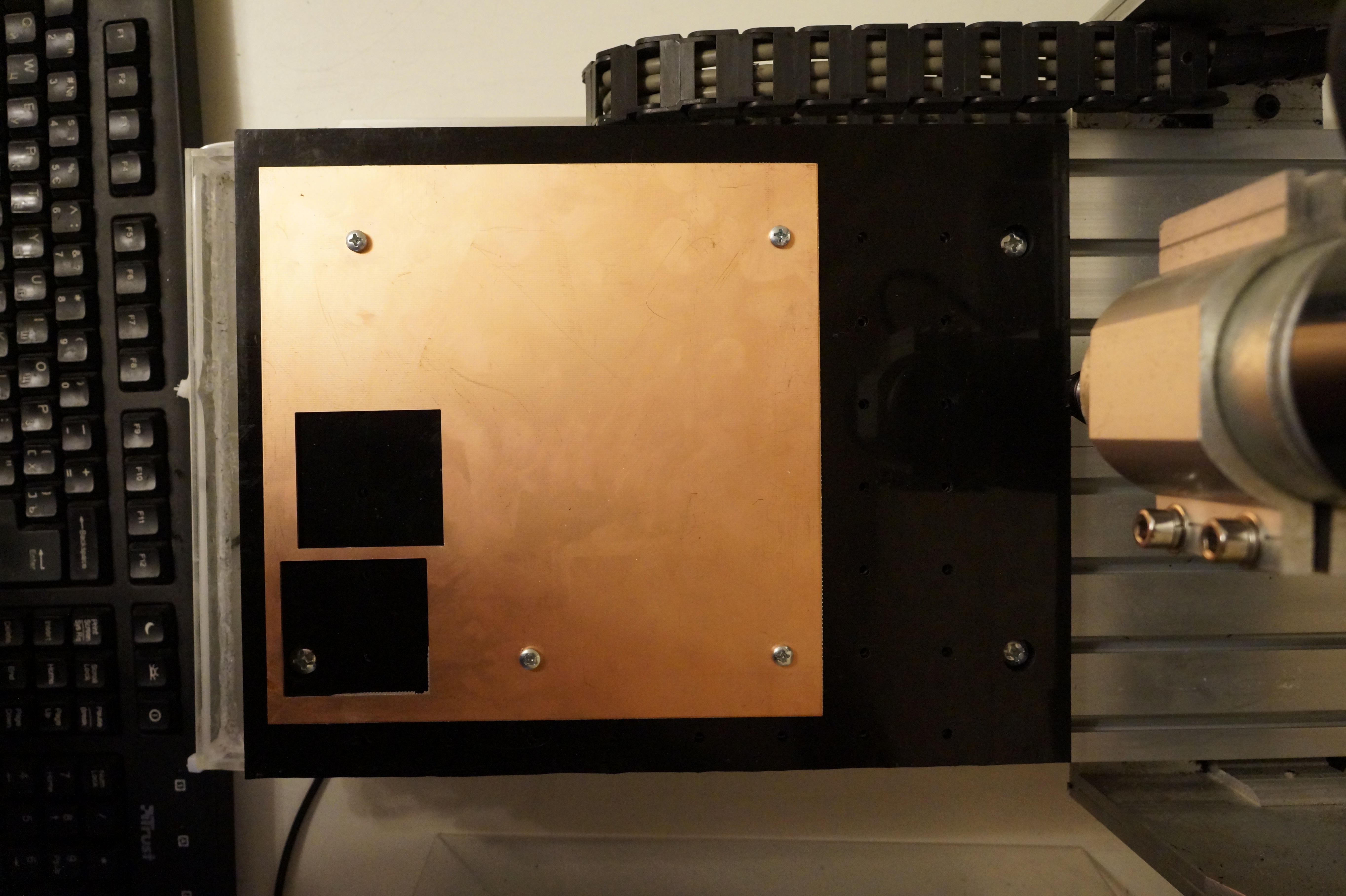
Fixing workpieces
I have tried several methods of fixing workpieces in the past. The problem is that the forces inflicted by cutting can be quite great; if the only counteracting force is friction, it will get slightly displaced.
So the simple and reliable solution is: just drill some holes in it and screw it down. I drill holes with a d=5mm drill to allow for some inaccuracy in marking the holes and flexibility of material.
Conclusions
- HDPE sheet is great for this kind of fixture; it is rigid and does not interact with coolant.
- Nuts fit tightly inside the pockets and do not get displaced.
- Offsetting nuts by 7.5mm allows a large margin for attaching materials of different thickness.
- Placing nuts over the T-slots allows the coolant to escape rather than get stale inside the pockets; nevertheless, nuts can slowly corrode over time.