MOSFET-based Gouriet-Clapp capacitive three-point oscillator
Tags:In this note I describe a Gouriet-Clapp capacitive three-point oscillator, which is an extremely simple circuit that produces high-frequency (~20-30MHz) electromagnetic field. It can light up gas discharge tubes and as such can be used to estimate pressure in vacuum systems.
Tools
- adjustable PSU
- Arksen 303D, 30V 3A
Materials
- power MOSFET
- IRF740A
- trimming potentiometer
- Bourns 3296W 2kΩ
- bypass capacitors
- 1µF 0805 ceramic, 100µF 16V tantalum
- tuning capacitor
- 22pF 0603 C0G 50V ceramic
- heatsink
- generic, for TO-220, 25W
- varnish-covered wire
- d=1mm
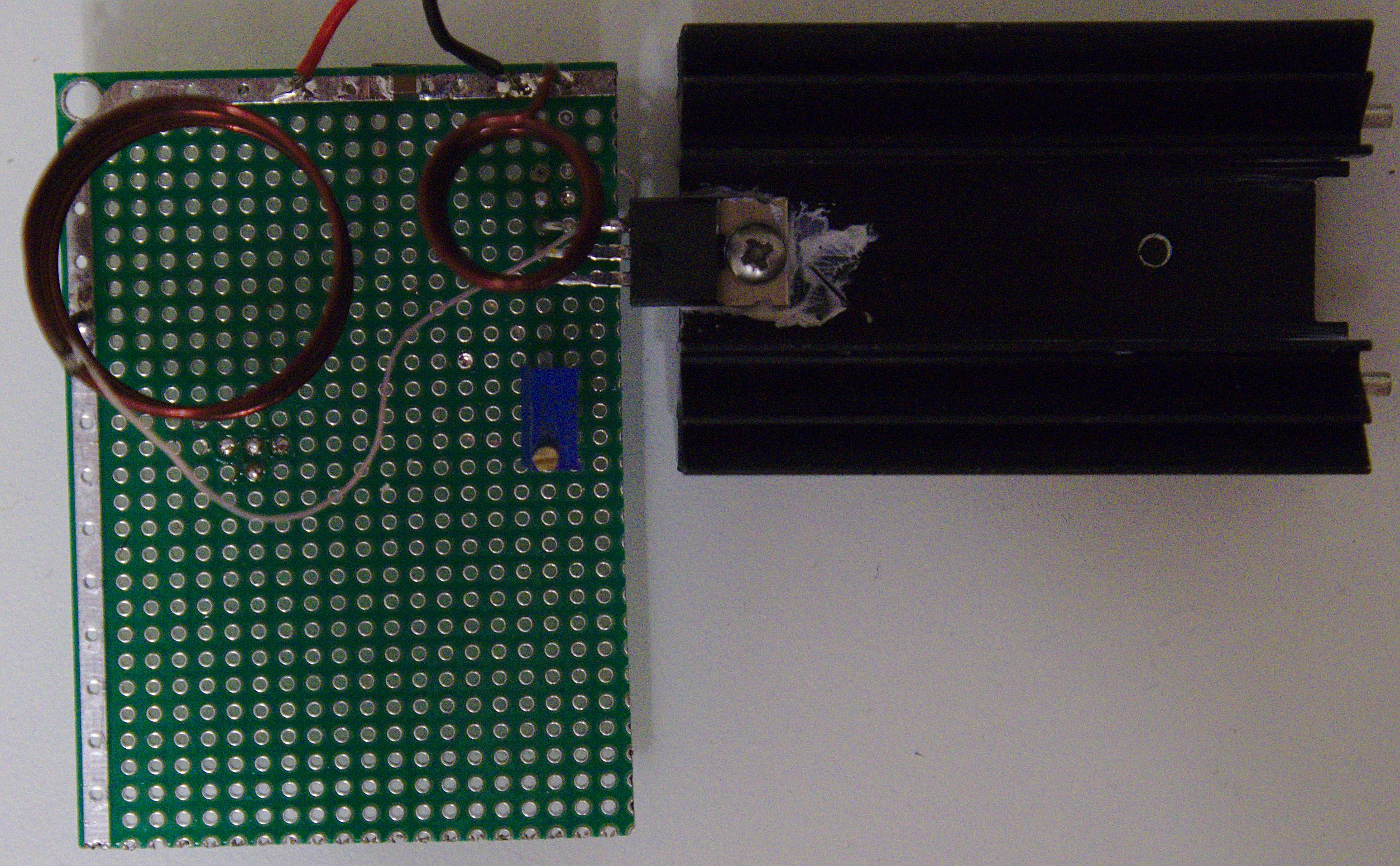
Construction
The circuit is very simple:
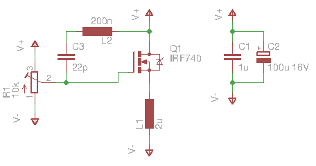
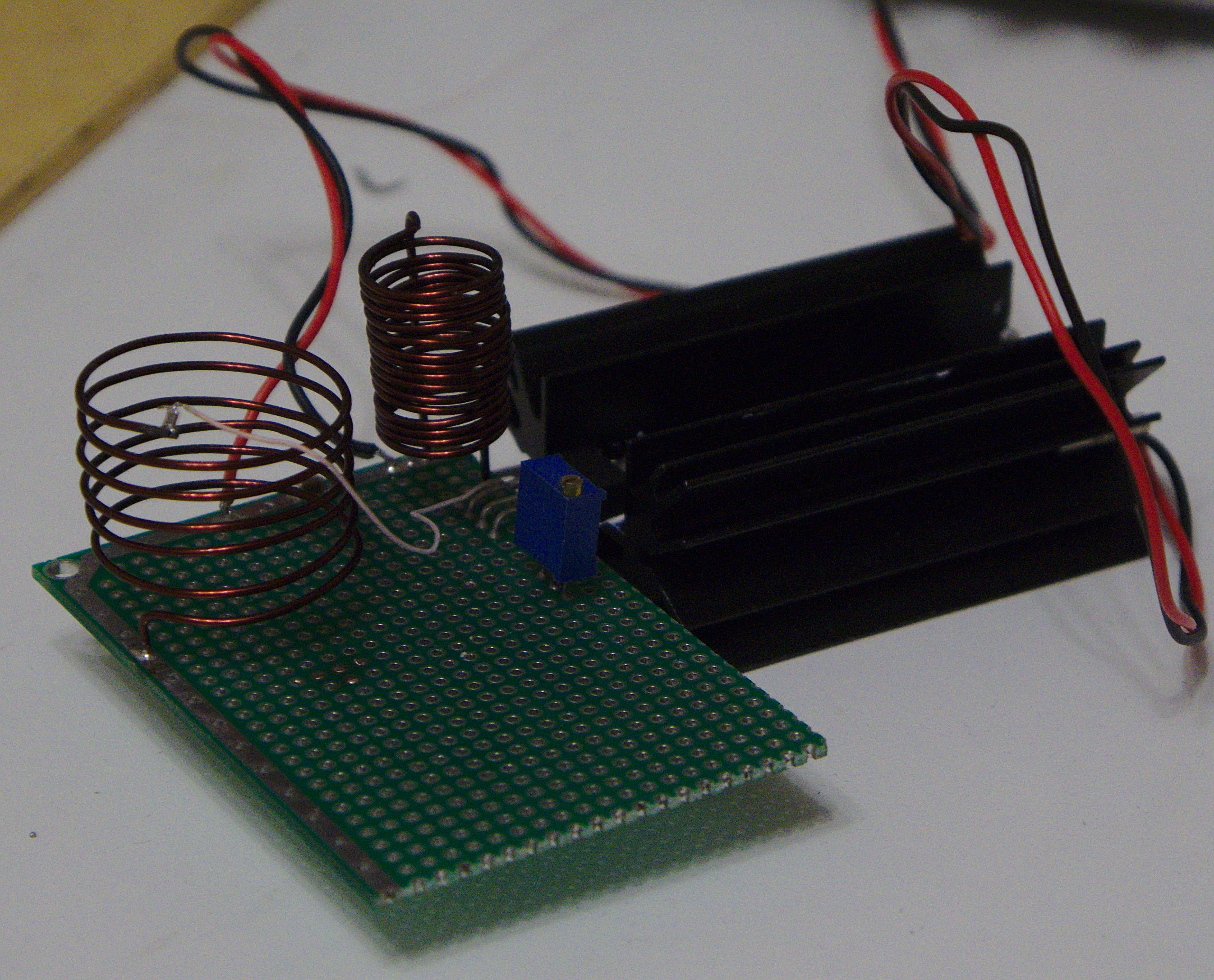
It will work with practically any power MOSFET that can switch fast enough; the L2-C3 resonant circuit should be tuned to ~27MHz. L1 and L2 are air-core inductors; L1 should be about 15 turns with d=10mm, and L2 about 6 turns with d=25mm. L2 turns should be well-spaced.
C3 should in principle be a high-voltage capacitor, as the voltage across L2 can be as high as 1kV, however I have found that a 0603 ceramic capacitor rated at mere 50V works very well. Before that, I have used a variety of DIY capacitors made out of Al foil or copper film on polyimide backing; these capacitors had dissipated so much heat they desoldered themselves from the coil. Puzzlingly, the ceramic one does not even appreciably heat up.
Operation
The circuit should be powered by an adjustable PSU in order to both control power consumption and calibrate it. Note that it exhibits highly nonlinear behavior that tends to produce oscillations in the PSU, and even when it does not, the PSU is unable to regulate its output well—in pathological cases, the controls simply affect nothing. Nevertheless, this has not damaged my PSU.
The circuit should start oscillating at ~15V. After assembling, set R1 so that the gate bias voltage is zero. Raise it until the circuit starts oscillating—when it does, the current should increase from nearly zero to 1-1.5A.
When tuned correctly, the circuit should oscillate at 27MHz. In my case, it oscillated at a suboptimal frequency of 32MHz, likely because the value of C3 was off.
When oscillating, the intense electromagnetic field it produces can light up CFL bulbs, or induce current in a single loop of wire:
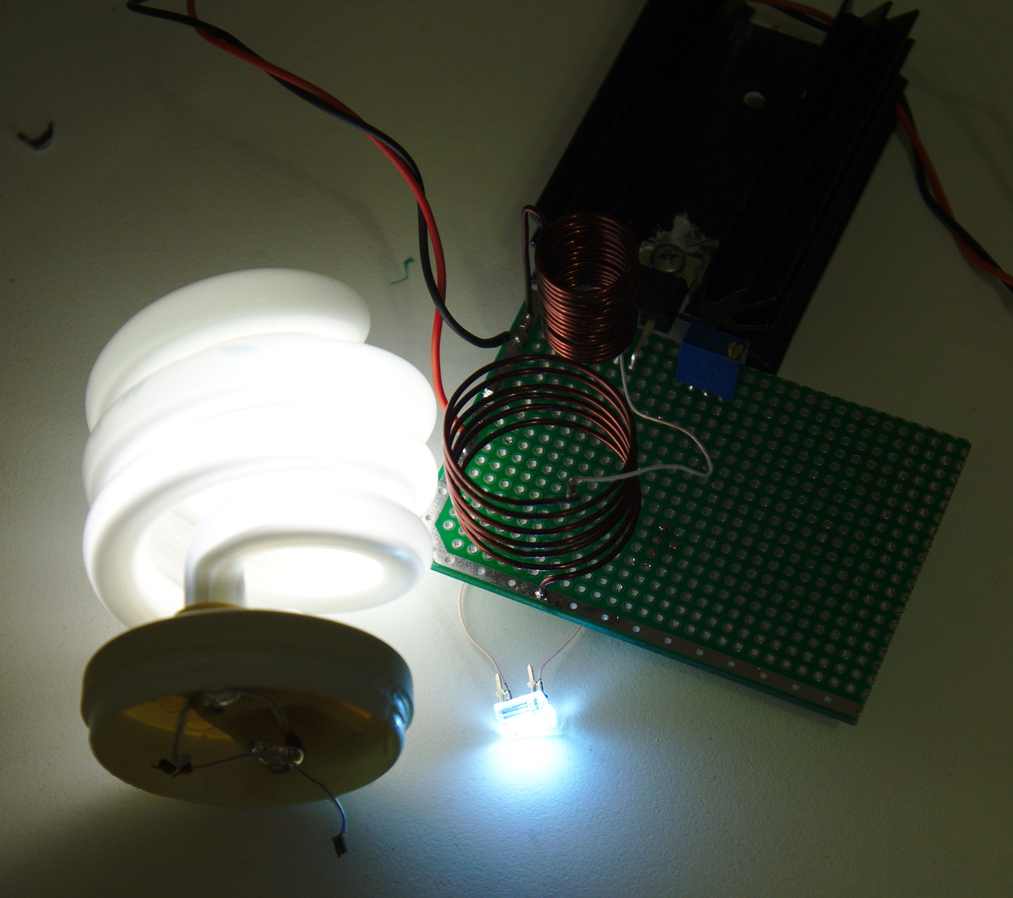
Note how placing a CFL bulb near the inductor increases the Q factor of the LC circuit, and the power consumption dramatically drops, sometimes by 30%.
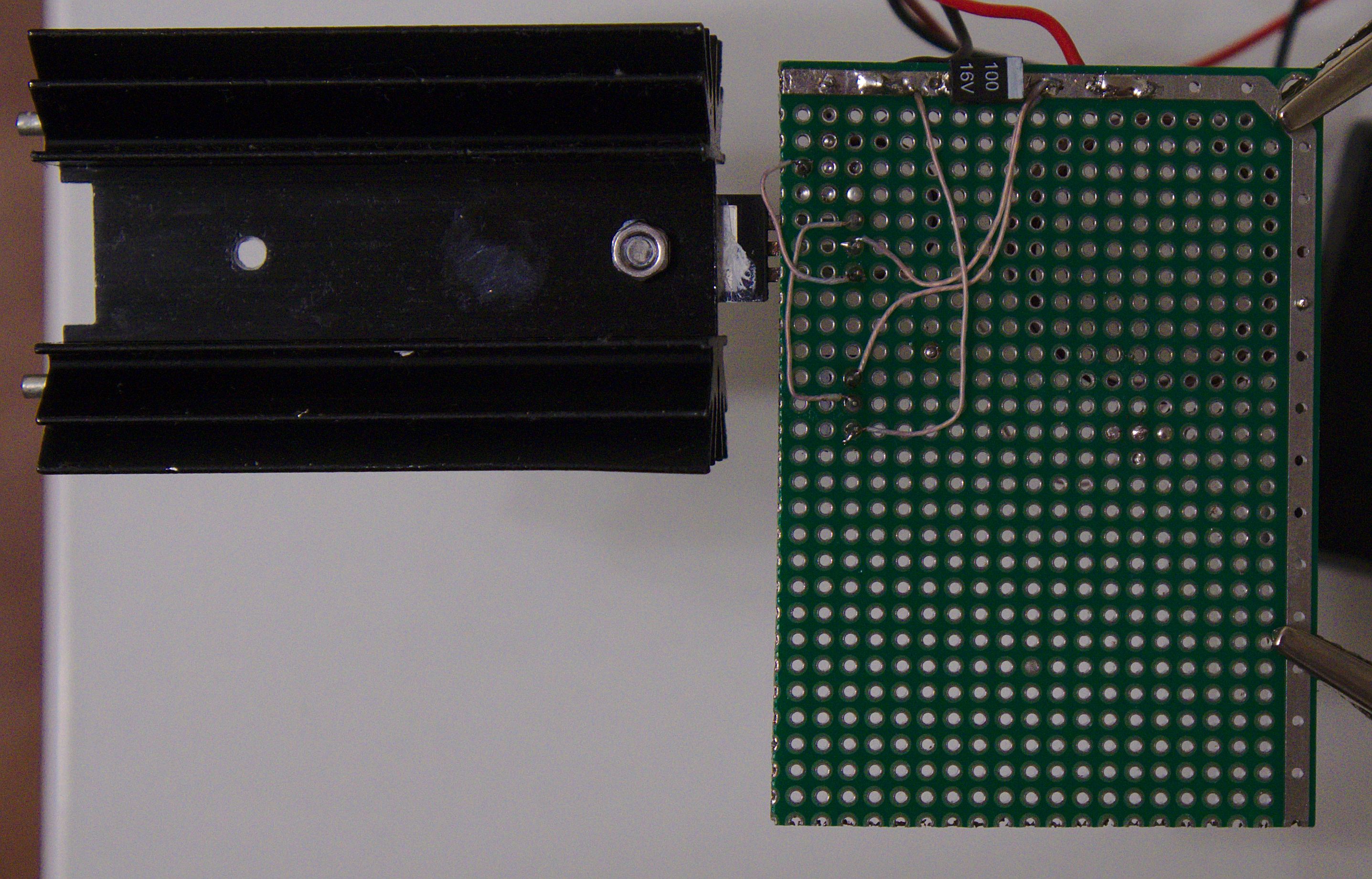
The main points of power dissipation are Q1 and L2. L2 heats somewhat, but not significantly. Q1 dissipates most of the consumed power. However, IRF740A is rated at 125W continuous, and while supplying the circuit ~60W of power makes it heat up to ~100°C, this is not a problem.
Make sure to not touch the hot heatsink, or the point between L2 and C3, where ~0.5-1kV is generated. This is not dangerous due to the skin effect, but quite painful, and the smell of burnt skin is unpleasant.
Interestingly, the operating circuit does not affect electronics noticeably. I’ve operated a laptop and a digital camera within 30cm of it with no effect whatsoever.
Principles of operation
The basic principles of operation are described in RF and Microwave Transmitter Design. The following is a similar circuit modelled in LTspice:
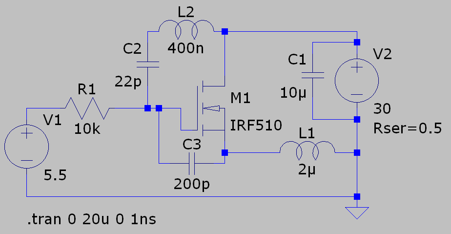
The circuit is unusual in that parasitic capacitance of the MOSFET, most importantly gate-source (modelled here as C3), is a crucial element of the design. Indeed, all the power passing through L2 has to pass through C2 and C3.