Measuring diode recovery time
Tags:After assembling a full-wave rectifier out of some 1A7 1kV-rated diodes, I noticed that it does not, in fact, rectify. I speculated that the diodes I used have a recovery time too high. Since it was not specified in the datasheet, I decided to measure it myself, which I describe in this note.
Background
Before a diode can conduct current forward, a space charge needs to be established across the p-n junction. After the external voltage is reversed, the diode will conduct in reverse for a certain time before the charge carriers recombine.
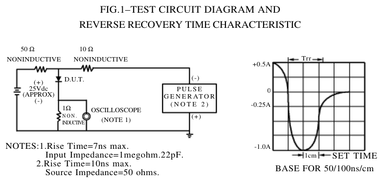
The following is a typical measurement circuit used in industry:
Simulation
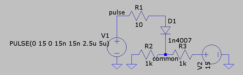
The following is the test circuit I use and simulation of its behavior:
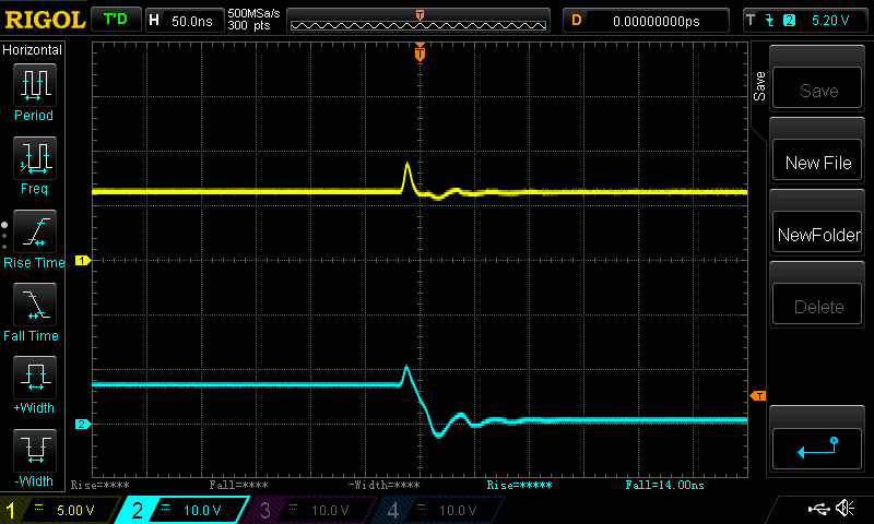
Measurement
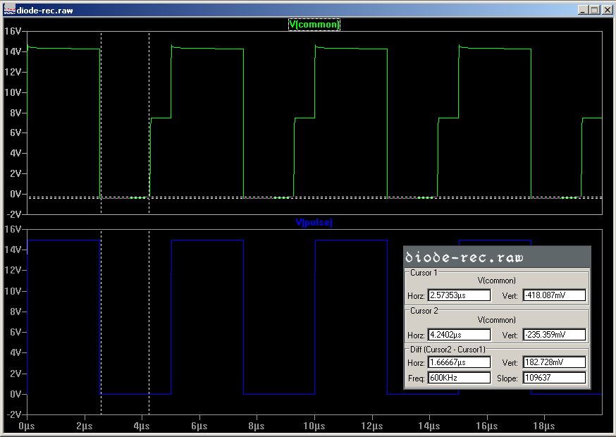
The circuit implements a pulse generator using a MOSFET half-bridge with the fall time of ~15ns and uses regular 0.125W thin film resistors. It is simple and reuses components I already had. The blue channel probes pulse and the yellow one probes common.
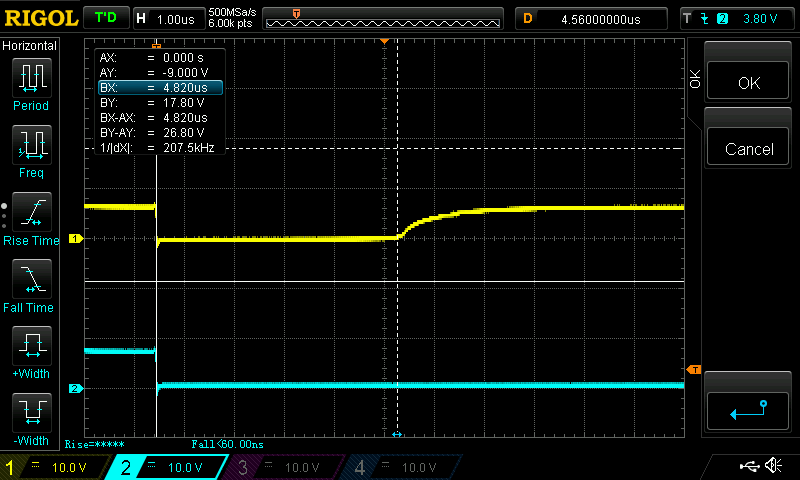
The DUT has a recovery time of about 7.5µs, which of course makes it useless in a rectifier
working at ~350kHz. (The cursors do not highlight the entire recovery interval.)
For comparison, these are the waveforms corresponding to 1N4148 (4ns recovery time) tested
using the same circuit:
My 150MHz oscilloscope probe is too crude to capture the pulse, not to mention there is too much parasitic inductance in the circuit anyway.