Ground loop in a lab power supply
Tags:Today, I decided to finally plug in my instruments properly, and plugged both my cheap lab PSU (ARKSEN 303D) and oscilloscope into sockets on the same strip with real ground prongs. After connecting the scope ground with the PSU negative rail, it quickly became clear that something’s wrong, because the wire connecting them went white-hot and sort of caught fire.
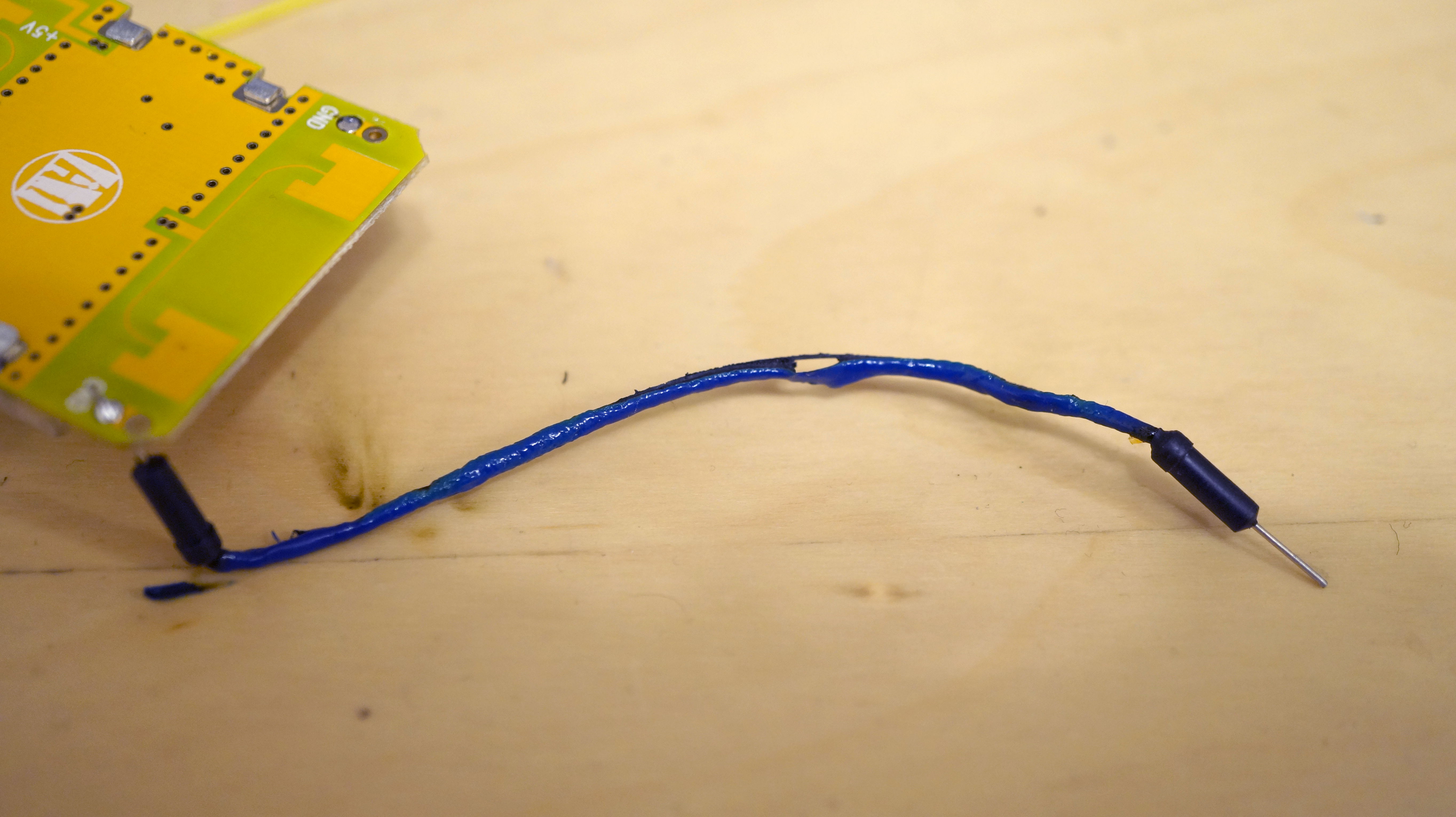
The PSU was limited at 50mA yet its amp meter went off scale during that.
(Incidentally, it might be a good idea to use these cheap breadboard wires as makeshift current limiters, because while it went white-hot, nothing else in the circuit got even warm. I would be much less happy had the oscilloscope probe melted.)
Anyway, I took out my DMM and figured out that the scope probe ground/case connects to the AC plug ground (about right), and there is a capacitor between PSU negative rail and PSU ground/AC plug ground (what.)
(How I could tell it’s a capacitor: when using a DMM in diode testing mode, it will beep for a while and then stop, then you can flip the leads and repeat that.)
Cracking it open:
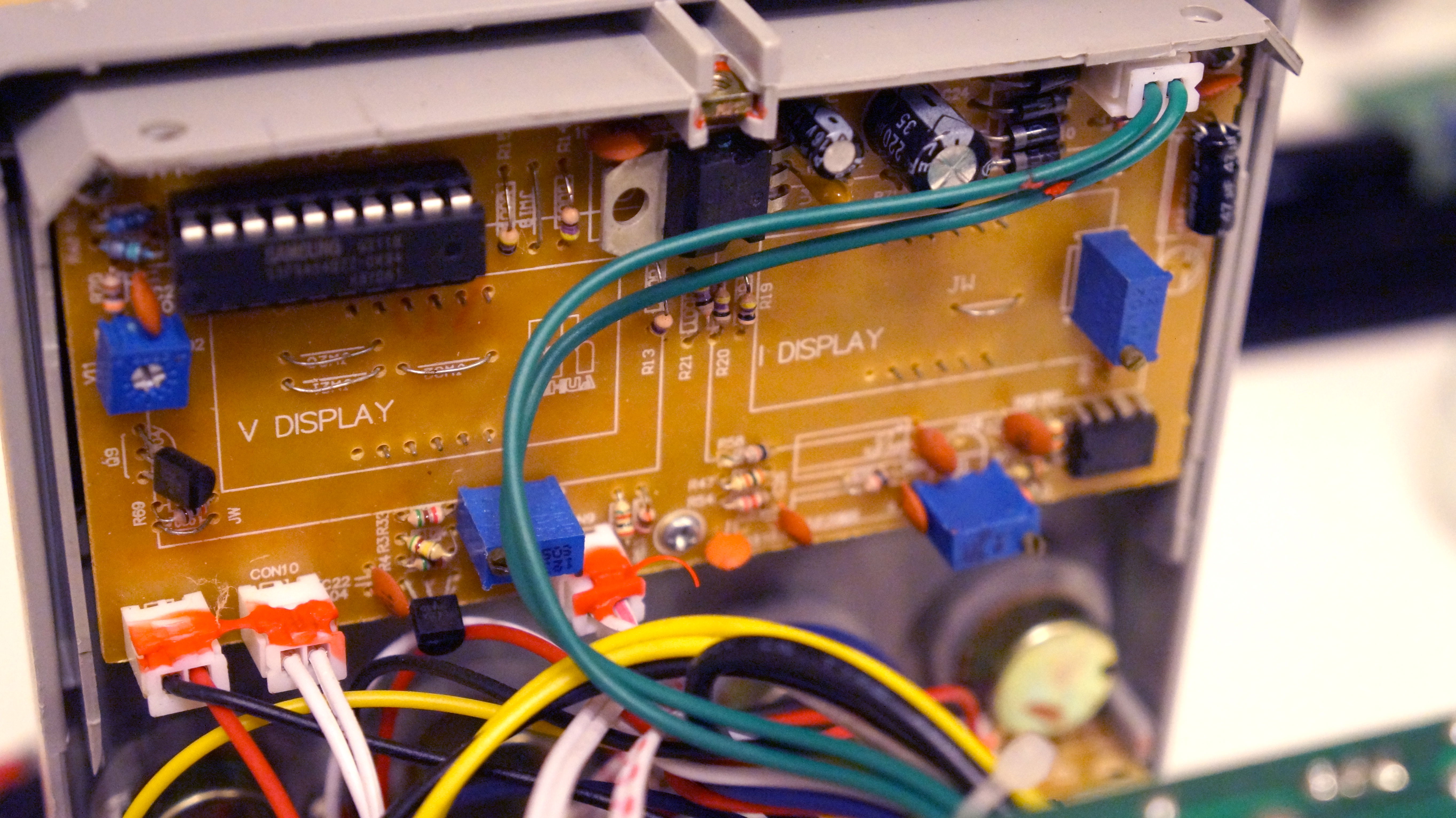
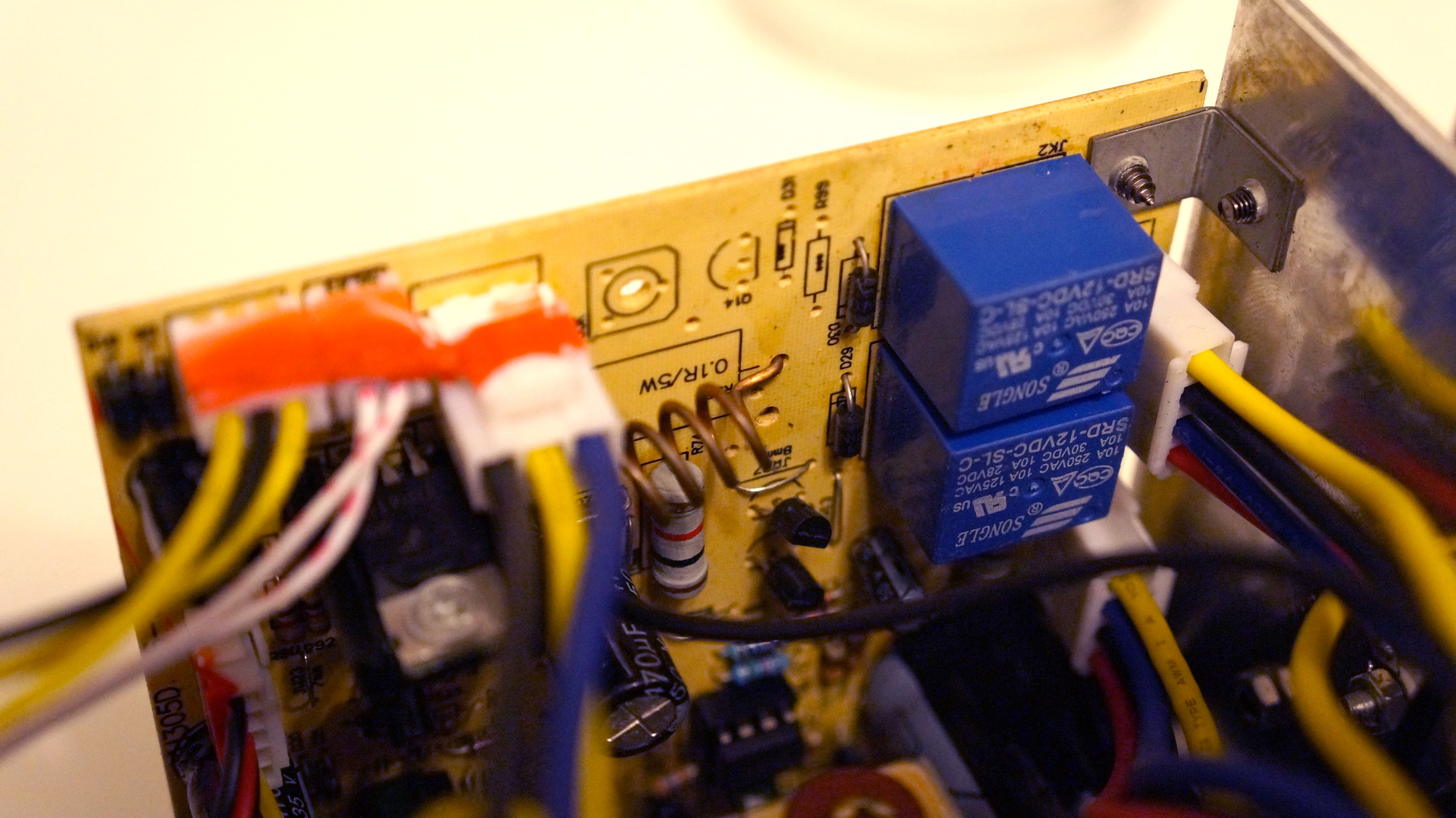
Someone should tell these people about the recent inventions, namely FETs, SMT components, switch-mode power supplies, double-sided PCBs, FR-4… The enormous transformer inside it was responsible for at least half of the substantial shipping cost.
The cause of the failure is almost immediately apparent: a badly routed PCB and one screw too tight. It shorts +15V (well, rectified 10Vac) to the grounded (by virtue of being screwed to the case) heatsink, thus driving the negative rail -15V relative to ground.
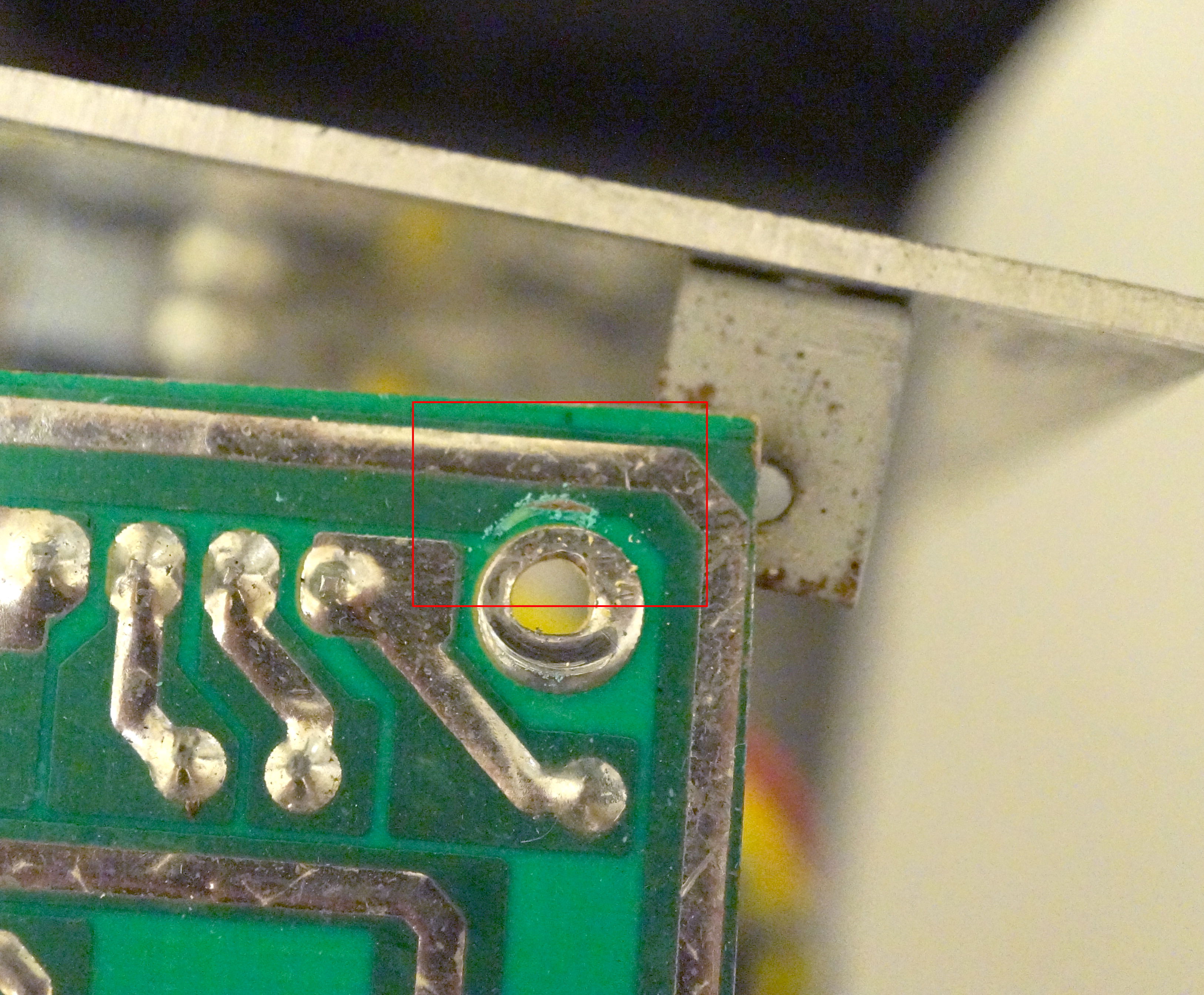
The failure is easily fixed with a chunk of mylar placed between the screw and the PCB. I’m left with a working PSU and sheer disappointment in its gross, ancient, poorly designed and poorly assembled innards.