CNC3020T: coolant pump and CCW rotation
Tags:In this note I explain the way to extend the 3020T CNC mill with a coolant pump (especially useful for milling plastic) and also, as a side effect, a spindle direction switch.
I have used a lot of locally-sourced components which will probably be unobtainable in other parts of the world. However, it should be trivial to find equivalent ones and adapt the instructions.
- Tools
- Materials (water sink)
- Materials (pump and piping)
- Materials (control board)
- Materials (mechanical)
- Materials (PCB manufacturing)
- G-code for container
- Assembling container
- Attaching container
- Adding water pump
- Table and water flow
- Designing control board
- Installing control board
Tools
- CNC machine
- CNC3020T
- d=0.6..1.5mm diamond-cut flat carbide endmill set
- generic
- electric drill
- generic
- d=3mm drill bit
- generic
- L=200mm diamond file set
- generic
- clamper/cutter
- generic
See also “Producing PCBs using photolithography”.
Materials (water sink)
- d=3mm thick clear cast acrylic sheet ×~1000cm²
- generic
- d=6mm HDPE plastic tube ×2cm
- generic
- Two-component epoxy
- BISON
- Transparent polymethylsiloxane-based sealant
- QUILOSA Orbasil
- 25x4.5mm nylon cable tie ×5
- generic
- flux container
- CT-006
- d=4mm D=6mm silicone hose ×2m
- generic
Materials (pump and piping)
- windshield washer pump
- for LADA-2110
- d=4mm D=6mm windshield washer hose ×3m
- for LADA-2110
- windshield washer tank
- for GAZ-24
- 6.3mm spade push on terminal (0.25-1.65mm wire) ×2
- SG57744
- M4x0.7x10 stainless steel hex cap screw
- generic
Materials (control board)
- adjustable 0~37V / 0~40V 3A buck converter
- MasterKit BM037M
- 834-1A-B-C, 24V 10A 1-closure relay
- Song Chuan
- TR99-24VDC-SB-CD, 24V 5A 2-switch relay
- Tai-shing Electronics Components
- l=5mm 2-pin screw terminal ×4
- 301-021-12, Xinya
- 1N4944 diode
- generic
- 1N4148 diode ×2
- generic
- PC827
- generic
- 390Ω 1/4W resistor ×2
- generic
- 4-pin pinhead
- generic
- 4-pin pinhead socket ×2
- generic
- 3.7mm U-type terminal (0.25-1.65mm wire) ×2
- generic
- 0.5mm² multistranded hookup wire ×2m
- generic
Materials (mechanical)
- M3x5 screw ×8
- generic
- M3x10 copper PCB stand ×8
- generic
- M3 nut ×8
- generic
Materials (PCB manufacturing)
See “Producing PCBs using photolithography”.
G-code for container
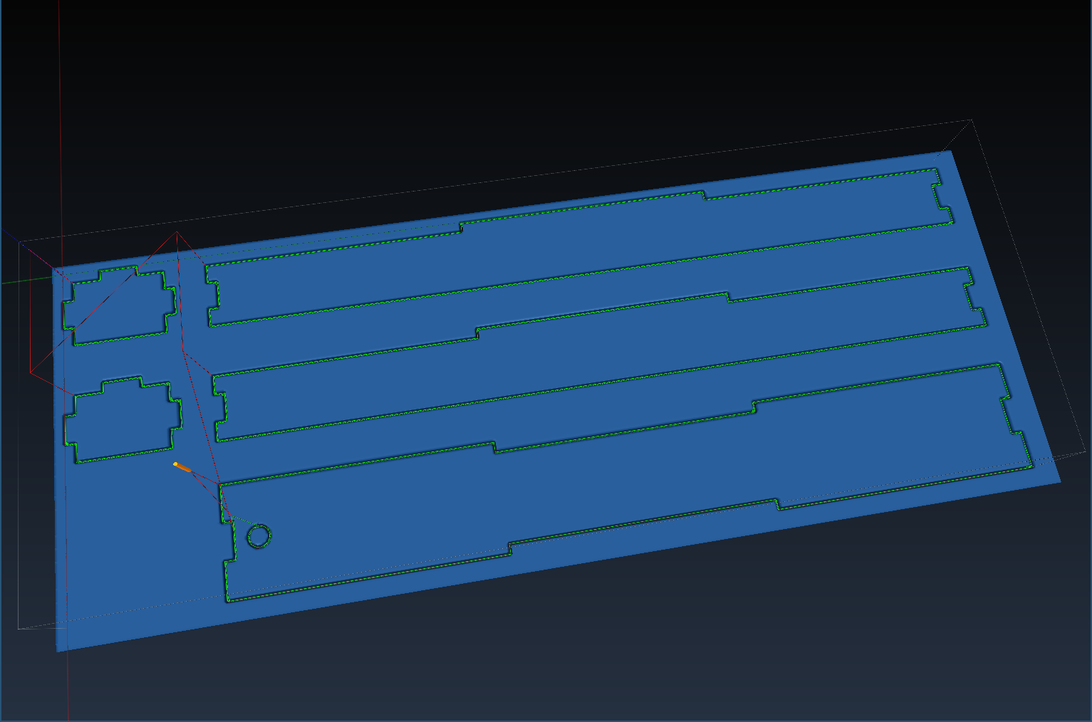
As usual, the G-code I publish is parametric; it can be easily customized for different material thickness, dimensions, etc, without the need for a proprietary CAM processor. Modify the “parameters” sections in the G-code and validate the result using OpenSCAM. The G-code will only work with LinuxCNC.
In this case, the G-code defines a tabbed plastic container to be glued, milled out of a material sheet #<_thickness> mm thick, using horizontal step #<_eps>.
1
2
3
4
5
6
7
8
9
10
11
12
13
14
15
16
17
18
19
20
21
22
23
24
25
26
27
28
29
30
31
32
33
34
35
36
37
38
39
40
41
42
43
44
45
46
47
48
49
50
51
52
53
54
55
56
57
58
59
60
61
62
63
64
65
66
67
68
69
70
71
72
73
74
75
76
77
78
79
80
81
82
83
84
85
86
87
88
89
90
91
92
93
94
95
96
97
98
99
100
101
102
103
104
105
106
107
108
109
110
111
112
113
114
115
116
117
118
119
120
121
122
123
124
125
126
127
128
129
130
131
132
133
134
135
136
137
138
139
140
141
142
143
144
145
146
147
148
149
150
151
152
153
154
155
156
157
158
159
160
161
162
163
164
165
166
167
168
169
170
171
172
173
174
175
176
177
178
179
180
181
182
183
184
185
186
187
188

; "Tabbed" container wall. Tabs comprise 1/3 of length.
; Optionally, tab on right edge may be omitted.
; Assumes G41
O<profile_step> sub
  #<width>  = #1
  #<length> = #2
  #<depth>  = #3
  #<xtab>   = #4 ; 0 or 1; 1 means tab, 0 means slot)
  #<ytab>   = #5 ; -//-
  #<flat>   = #6
  #<init>   = #7 ; 0 or 1; 1 means initial plunge

  ; Initial point
  G0 X[#<xtab> * #<_thickness>] Y[#<ytab> * #<_thickness>]
  O100 if [#<init>]
    G0 Z0
  O100 endif
  G1 F#<_plunge> Z#<depth>

  ; Left edge
  F#<_feed>
  Y[#<length> / 3]
  X[[1 - #<xtab>] * #<_thickness>]
  Y[#<length> / 3 * 2]
  X[#<xtab> * #<_thickness>]
  Y[#<length> - [#<ytab> * #<_thickness>]]

  ; Top edge
  X[#<width> / 3]
  Y[#<length> - [1 - #<ytab>] * #<_thickness>]
  X[#<width> / 3 * 2]
  Y[#<length> - #<ytab> * #<_thickness>]
  X[#<width> - [#<xtab> * #<_thickness>]]

  ; Right edge
  O110 if [#<flat>]
    Y[#<ytab> * #<_thickness>]
  O110 else
    Y[#<length> / 3 * 2]
    X[#<width> - [1 - #<xtab> ] * #<_thickness>]
    Y[#<length> / 3]
    X[#<width> - #<xtab> * #<_thickness>]
    Y[#<ytab> * #<_thickness>]
  O110 endif

  ; Bottom edge
  X[#<width> / 3 * 2]
  Y[[1 - #<ytab>] * #<_thickness>]
  X[#<width> / 3]
  Y[#<ytab> * #<_thickness>]
  X[#<xtab> * #<_thickness>]
O<profile_step> endsub

; "Tabbed" container wall. Tabs comprise 1/3 of length.
O<profile> sub
  #<width>  = #1
  #<length> = #2
  #<xtab>   = #3 ; 0 or 1; 1 means tab, 0 means slot)
  #<ytab>   = #4 ; -//-
  #<flat>   = #5 ; 0 or 1; 1 means no right tab

  #<depth>  = [-#<_step>]
  #<init>   = 1

  G41 ; Cutter compensation to the left

  O100 while [#<depth> GE -#<_thickness>]
    O<profile_step> call [#<width>] [#<length>] [#<depth>] [#<xtab>] [#<ytab>] [#<flat>] [#<init>]

    #<depth> = [#<depth> - #<_step>]
    #<init>  = 0
  O100 endwhile

  O110 if [#<depth> NE -#<_thickness>]
    O<profile_step> call [#<width>] [#<length>] [-#<_thickness>] [#<xtab>] [#<ytab>] [#<flat>] [0]
  O110 endif

  G40

  ; Pause between workpieces
  G0 Z#<_zsafe>
  M1

O<profile> endsub

; Offset G55 coordinate system based on G54
O<translate> sub
  #<dx> = #1
  #<dy> = #2

  G10 L2 P2 X[#5221 + #<dx>] Y[#5222 + #<dy>] Z#5223 R#5230

O<translate> endsub

; Helix-mill a hole.
; Assumes metric, XY plane, feedrate, and tool diameter are set.
O<helix_mill> sub
  #<xcenter> = #1 ( [mm] X center         )
  #<ycenter> = #2 ( [mm] Y center         )
  #<radius>  = #3 ( [mm] Hole radius      )
  #<zstart>  = #4 ( [mm] Z start position )
  #<zend>    = #5 ( [mm] Z end position   )

  G0 X#<xcenter> Y#<ycenter>
  #<znow> = #<zstart>

  G42 ; Cutter compensation to the right

  ; Cutter compensation entry
  F#<_feed>
  G1 X[ #<xcenter> - #<radius> ] Y#<ycenter>
  G1 Z#<zstart>

  ; Mill out body with several full helical turns
  O100 while [ #<znow> GT [ #<zend> + #<_step> ] ]

    #<znow> = [ #<znow> - #<_step> ]
    G2 I#<radius> J0 Z#<znow>

  O100 endwhile

  G2 I#<radius> J0 Z#<zend>

  ; Flat out the bottom
  G2 I#<radius> J0

  G40

  G0 Z#<_zsafe>

O<helix_mill> endsub

( === BEGIN PARAMETERS === )

; Metric, Absolute, XY plane
G21 G90 G17

; Safe Z level (above workpiece)
#<_zsafe>      = 25.

; Feeds/speeds for milling acrylic. *DO NOT FORGET COOLANT*
S7000
#<_thickness>  = 3.
#<_step>       = 0.4
#<_feed>       = 600.
#<_plunge>     = 100.

; Box size
#<width>       = 240.  ; X
#<length>      = 33.   ; Y
#<height>      = 26.   ; Z

; Outflow pipe radius
#<rpipe>       = 3.

; Offset between workpieces
#<offset>      = 10.

( === END PARAMETERS === )

; G54 contains base offset, G55 is for current workpiece
G55

T1 M6 ; 1mm cylindrical
M3    ; Spindle on

; Left/right walls
O<translate>  call [0] [0]
O<profile>    call [#<height>] [#<length>] [1] [1] [1] ; xtab ytab flat
O<translate>  call [#<height> + #<offset>] [0]
O<profile>    call [#<height>] [#<length>] [1] [1] [1]

; Front/back walls
O<translate>  call [0] [#<length> + #<offset>]
O<profile>    call [#<height>] [#<width>] [1] [0] [1] ; xtab !ytab flat
O<translate>  call [#<height> + #<offset>] [#<length> + #<offset>]
O<profile>    call [#<height>] [#<width>] [1] [0] [1]

; Bottom wall
O<translate>  call [[#<height> + #<offset>] * 2] [#<length> + #<offset>]
O<helix_mill> call [#<length> / 2] [10.0] [#<rpipe>] [0] [-3.0]
O<profile>    call [#<length>] [#<width>] [0] [0] [0] ; !xtab !ytab !flat

; Finalize
G0 Z#<_zsafe>
G54

M2
Visualization:
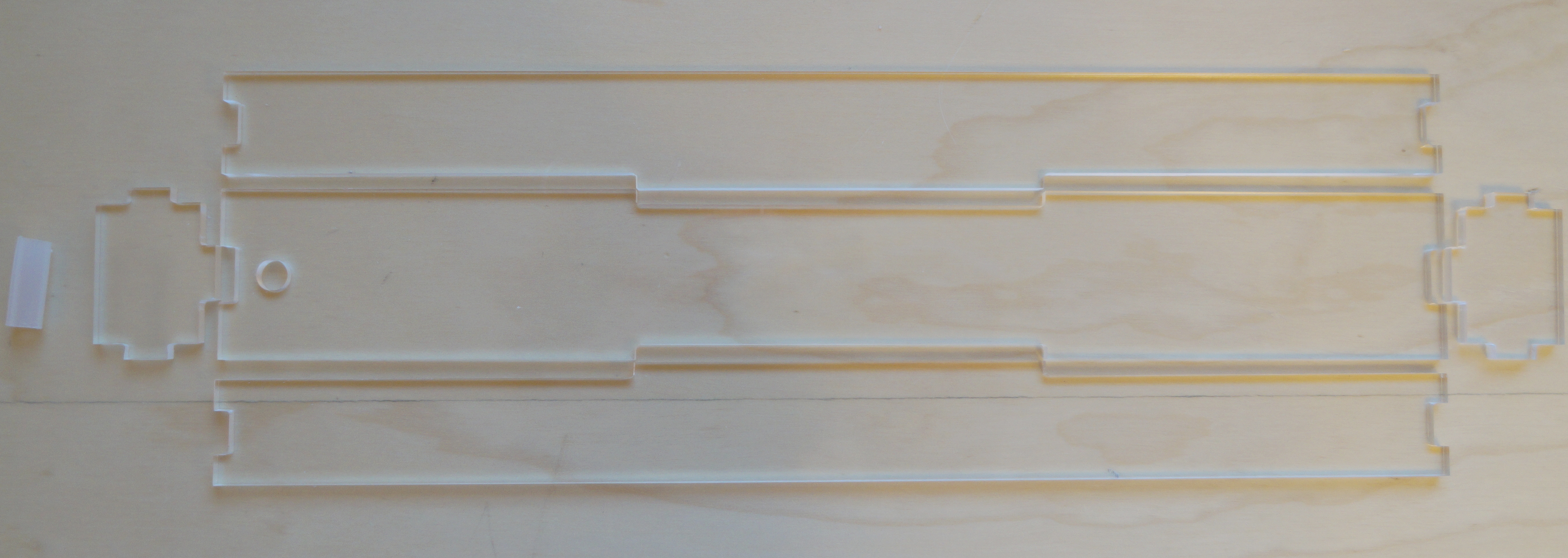
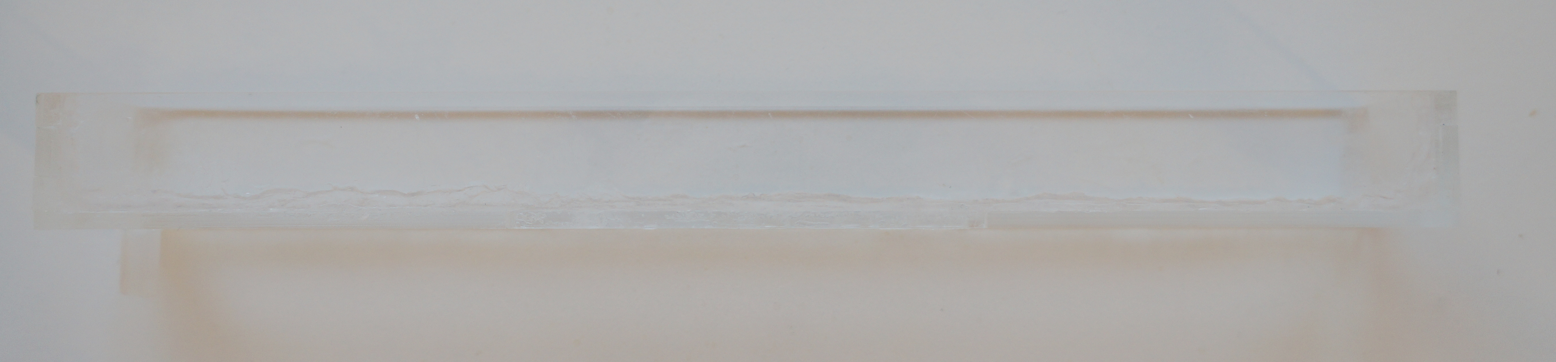
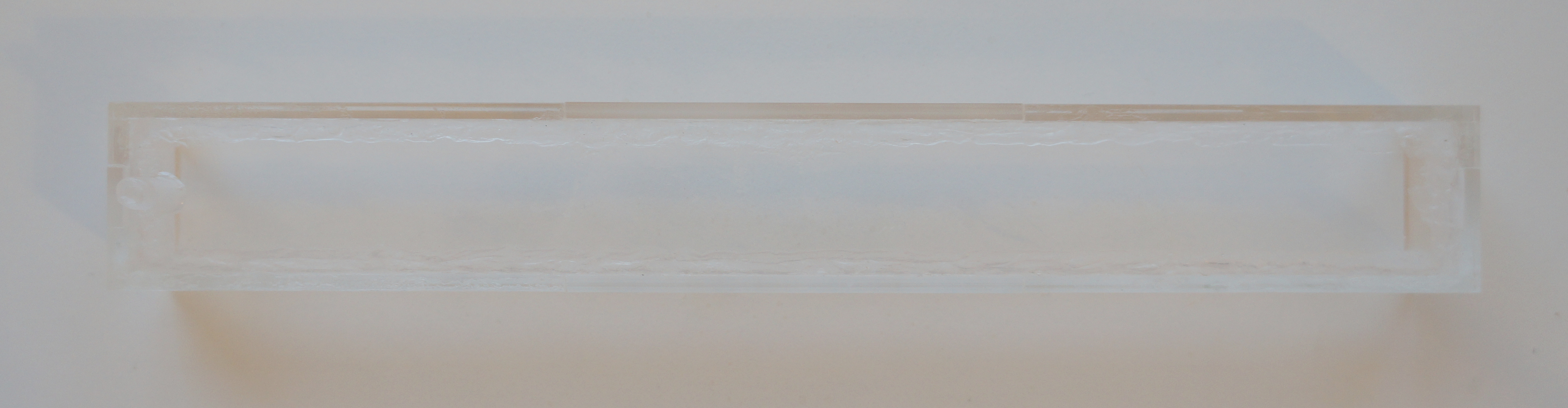
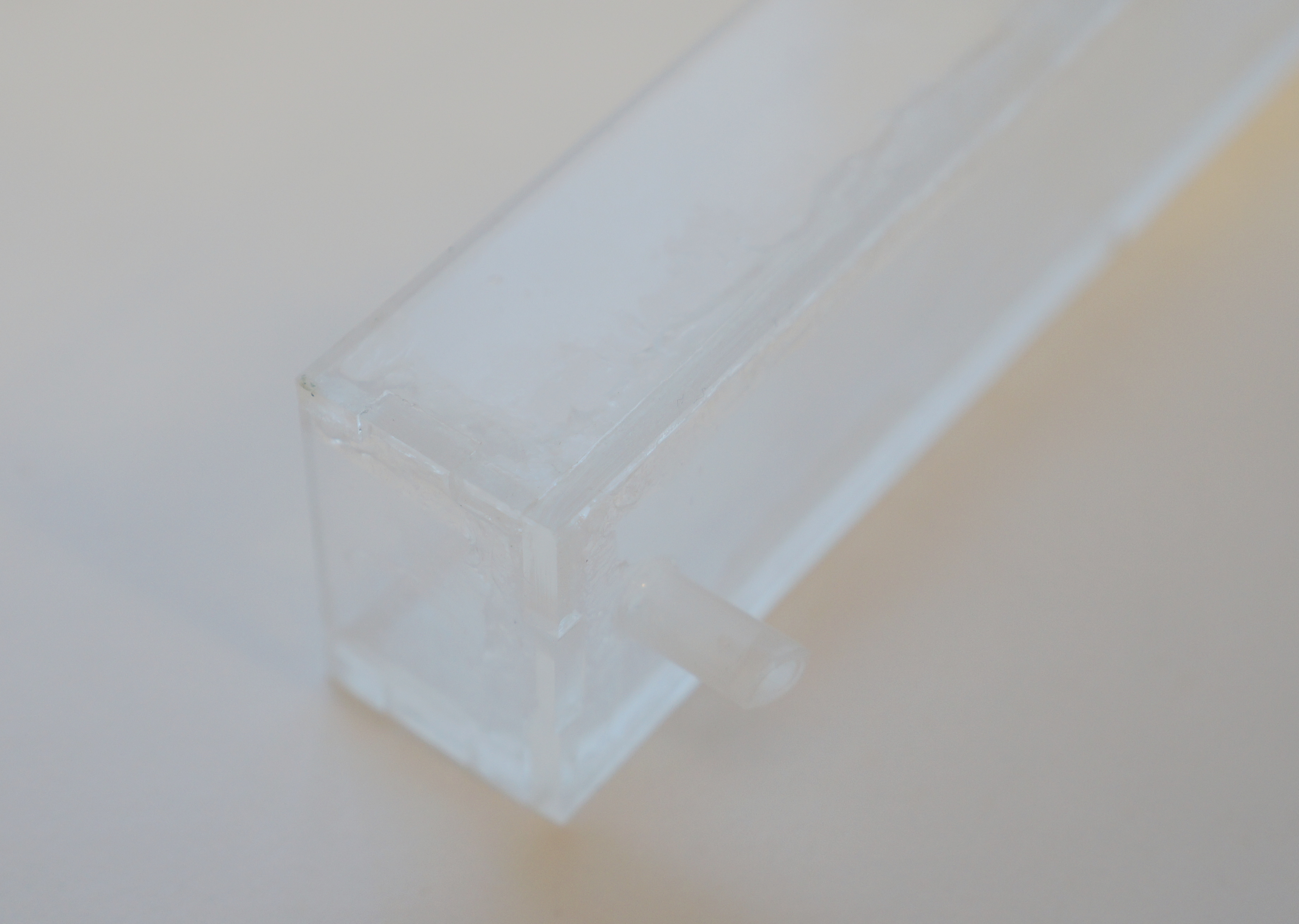
Assembling container
After milling, the concave corners have to be filed down in order for the sides to fit together. After that, the container can be glued together with epoxy. In my experience it is very hard to make it fully waterproof using just epoxy, so afterwards I have sealed it with silicone.
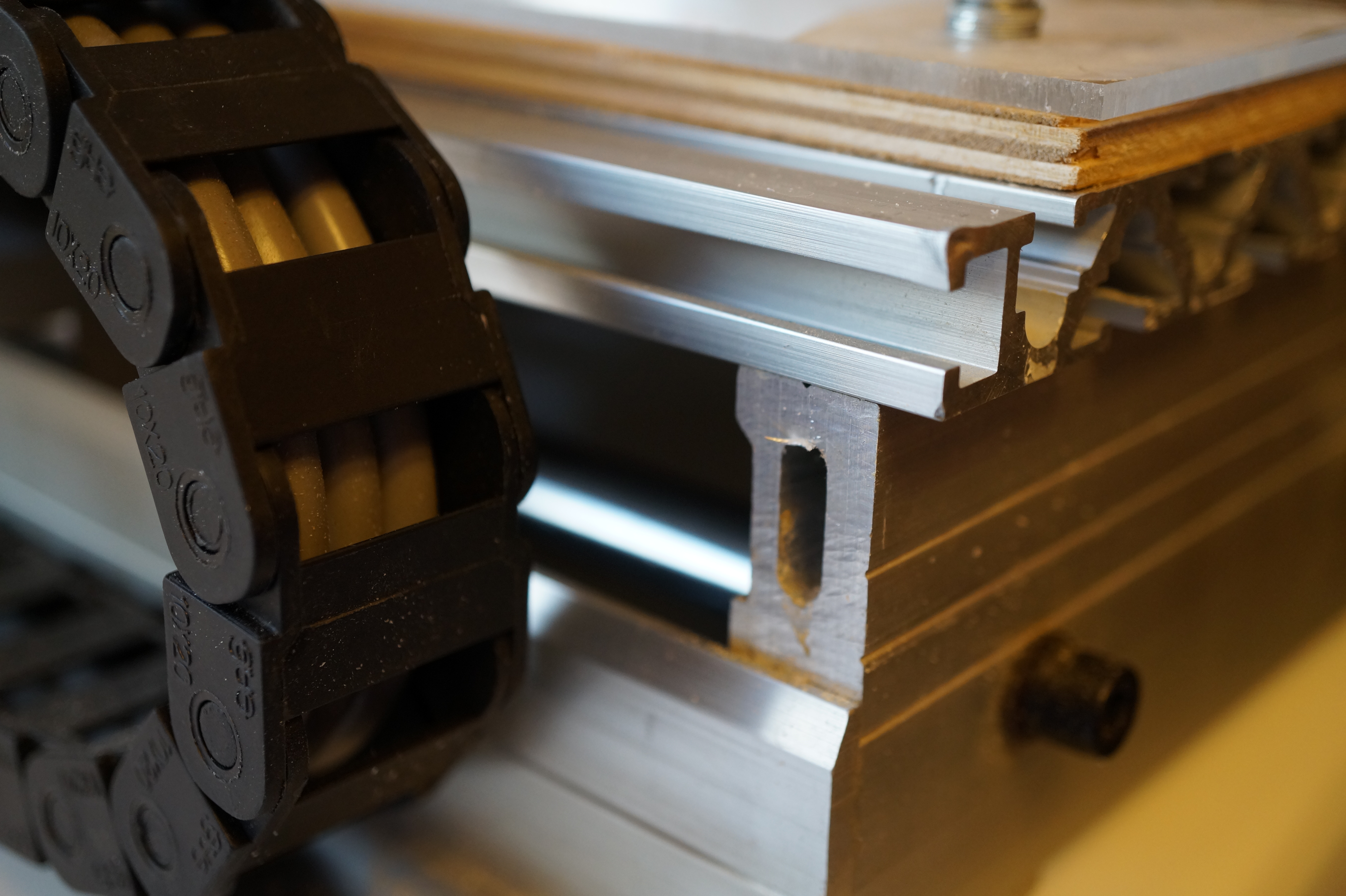
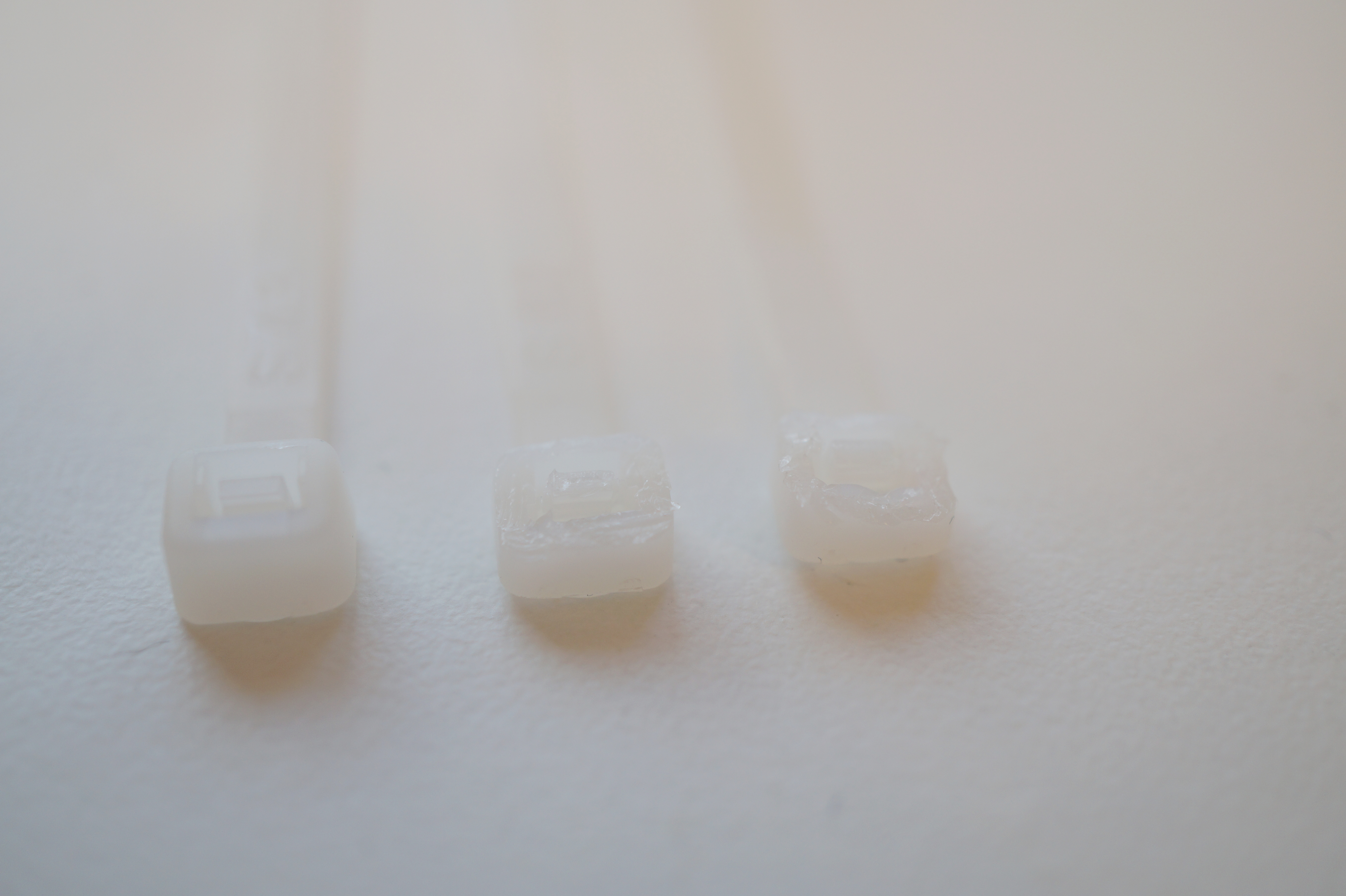
Attaching container
The CNC mill has a very conveniently located hole that allows to insert a chain of three nylon cable ties inside to fix the container under the table. I had to cut down the cable ties’ latches, as they were somewhat too wide to pass through the hole.
The silicon hose can be easily attached to the pipe
Adding water pump
In order to make a nozzle, I have cut the outside part of the CT-006 flux container, heated it up with a hot air gun at ~200°C, and straightened it until it was bent at about 120°. Then, I have heated the hose in the similar way and attached it to the straightened nozzle.
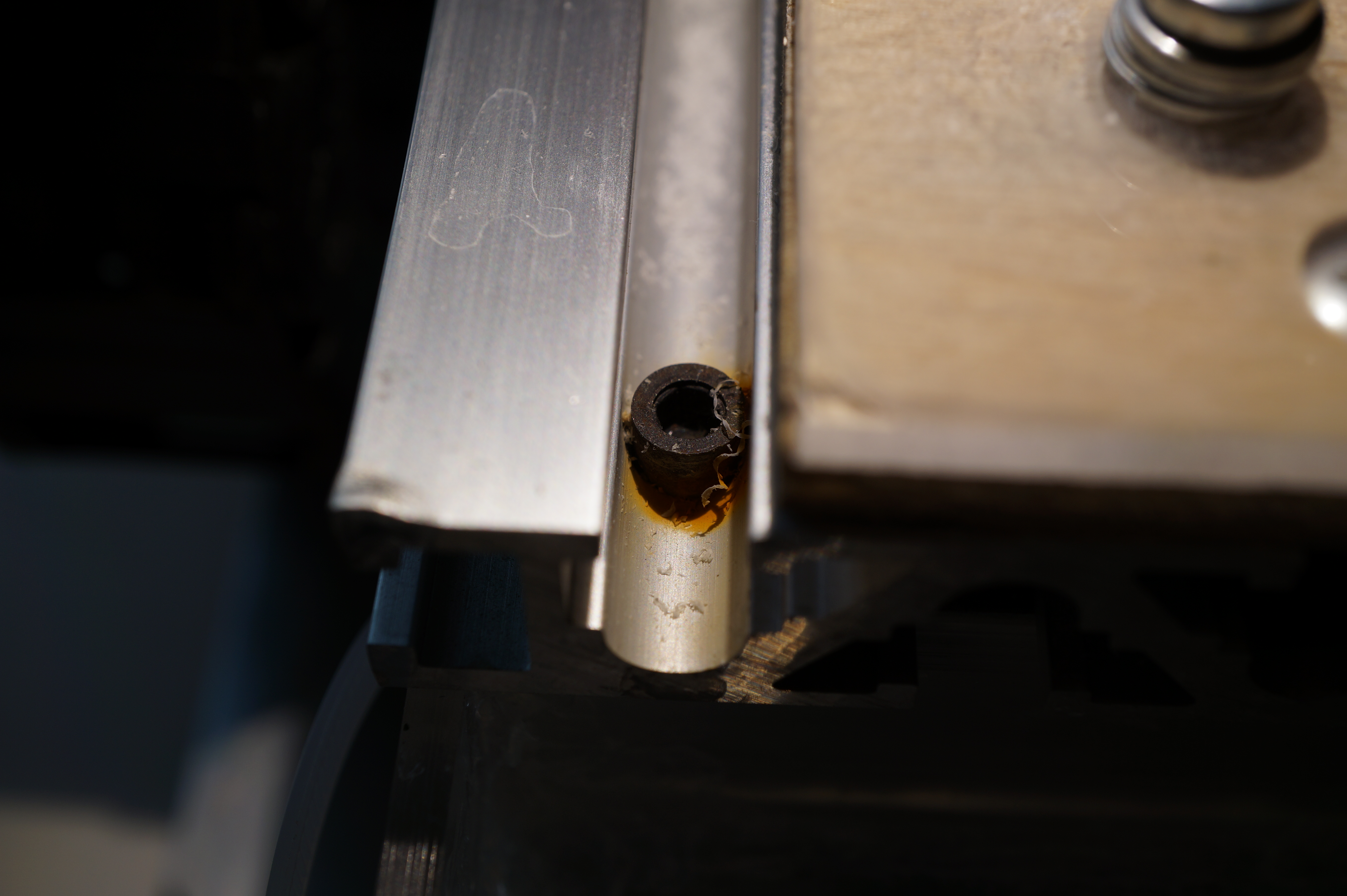
In order to fix the hose to the CNC mill frame, I used the cable ties. However, the spindle has some convenient grooves, into which you can squeeze the hose; this has the advantage that it is fixed very securely and does not move when the mill traverses, yet it can be easily adjusted for pointing the flow in the desired direction.
Note that the pump leaks like crazy. I have never seen such a shitty piece of engineering. However, disassembling it (it’s made of three snap-on injection molded parts) and liberally applying silicone mostly stops leakage. The connection between the pump and the water tank may also need sealing.


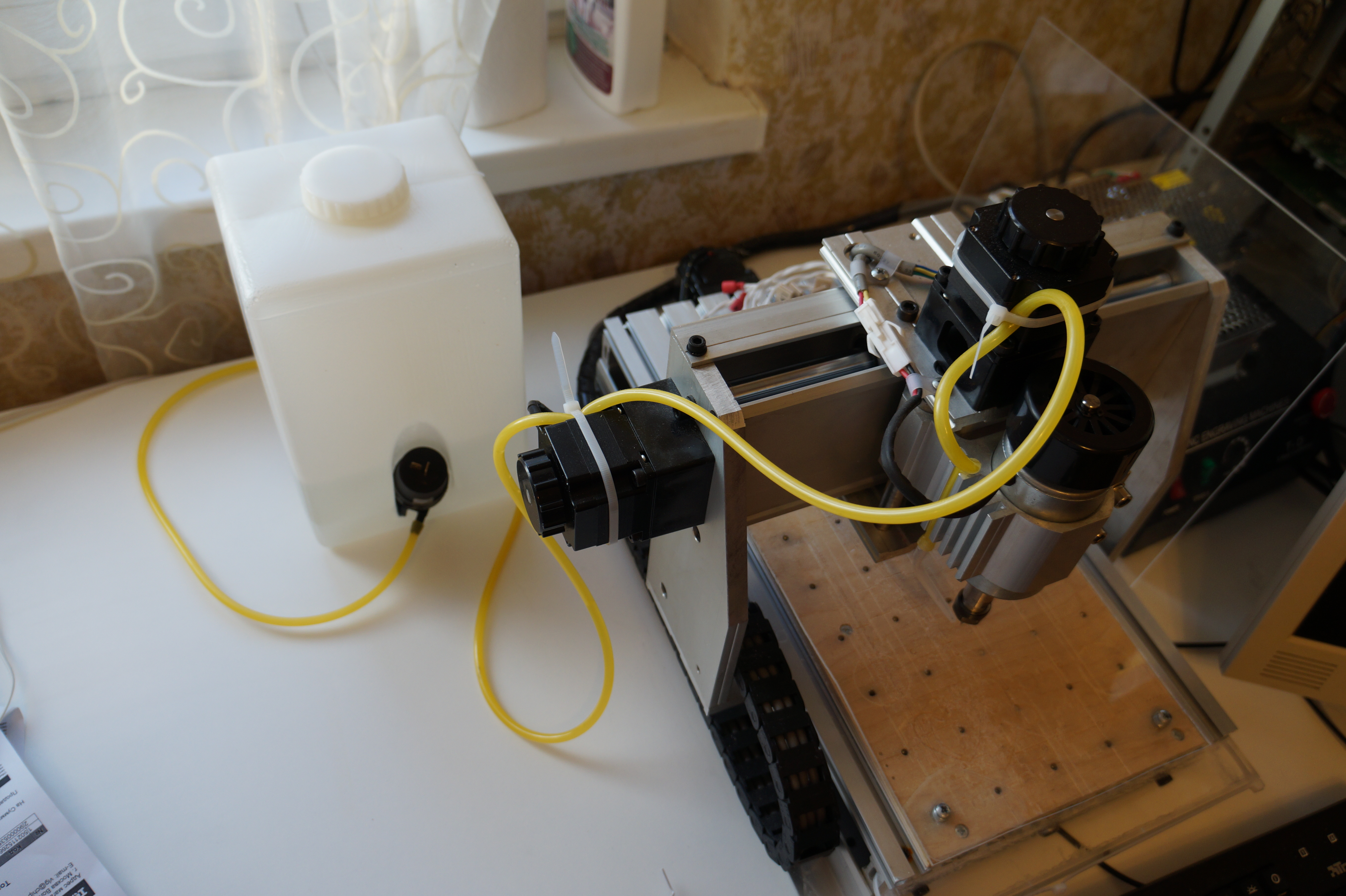
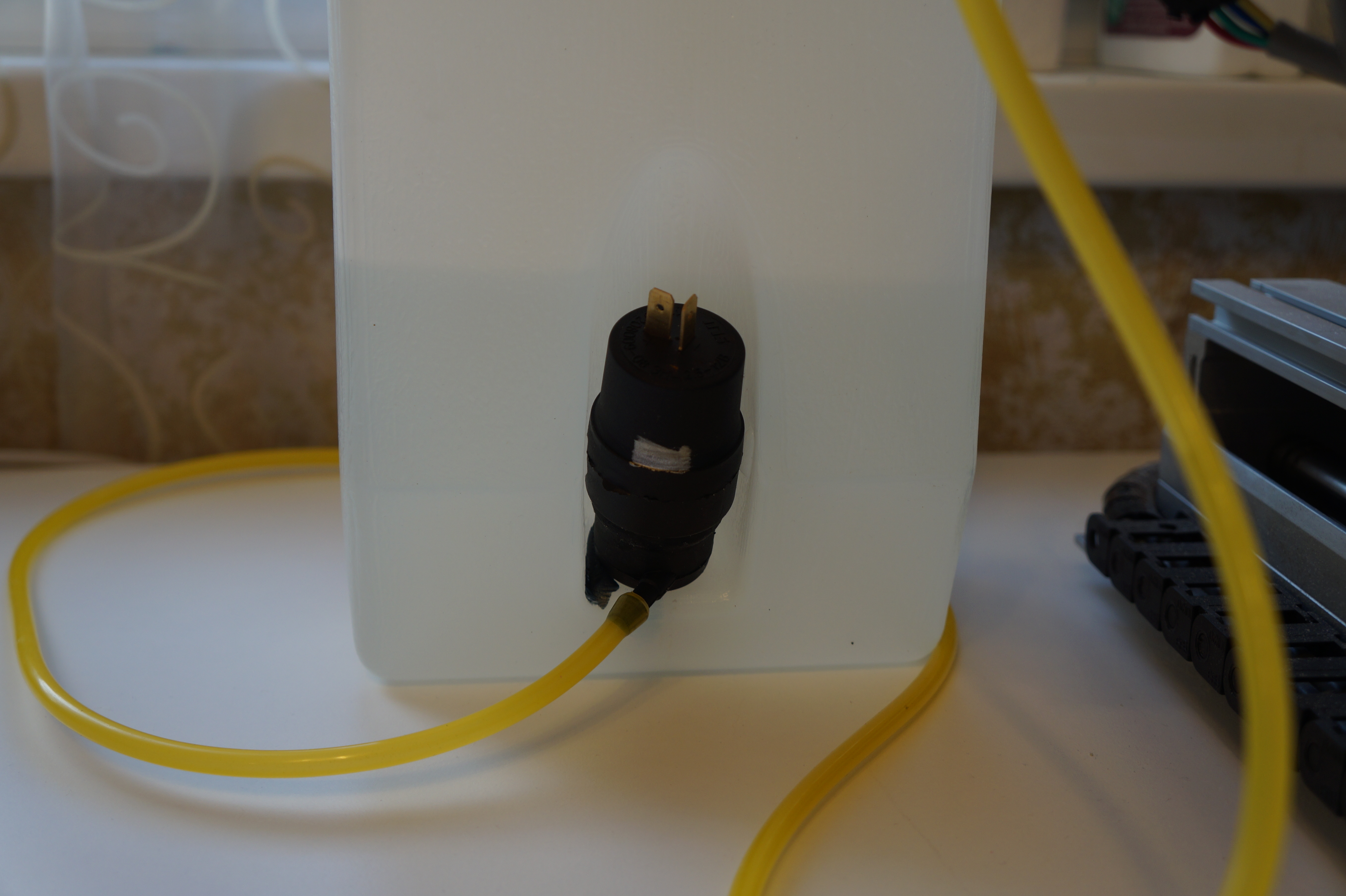
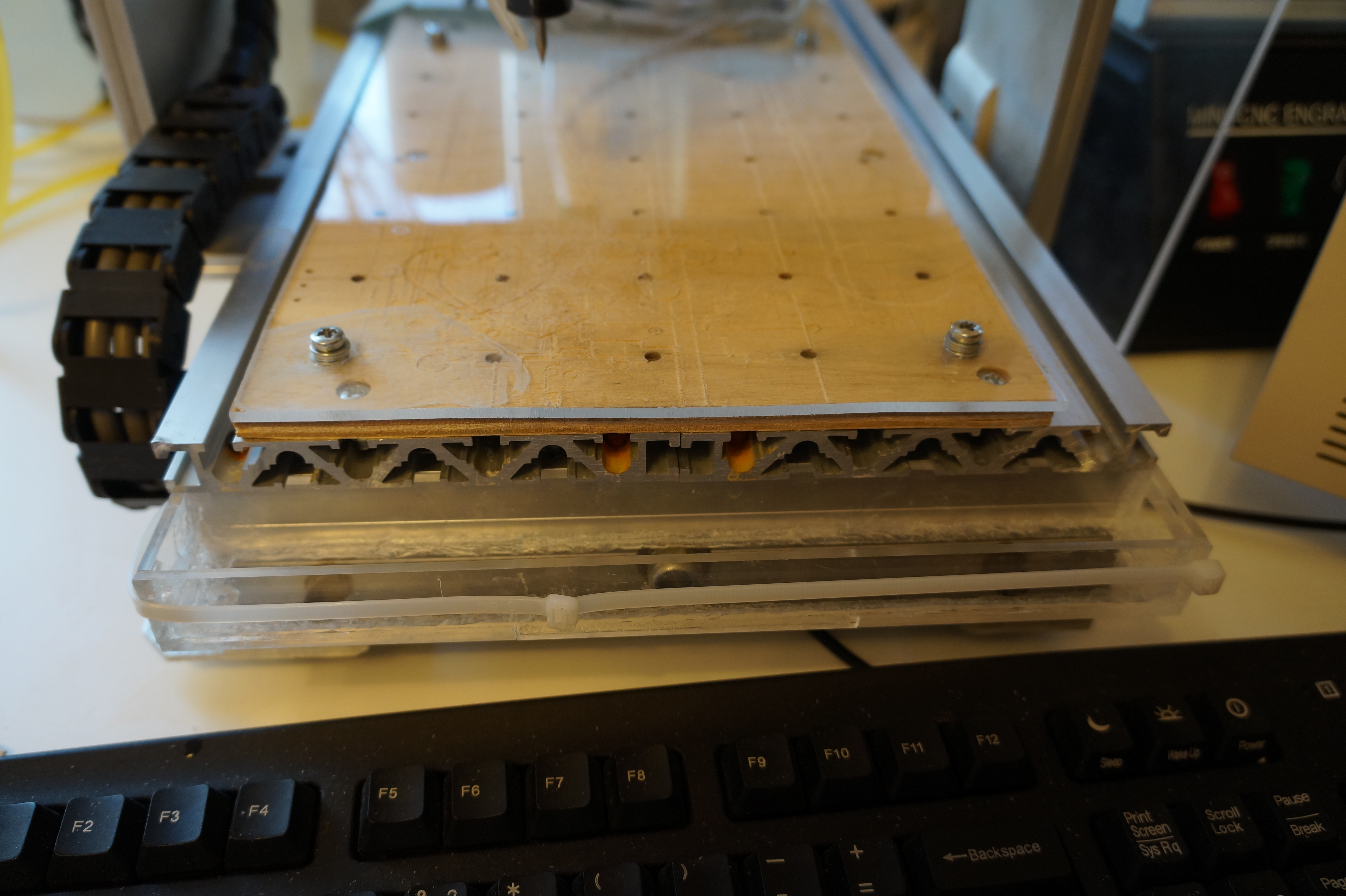
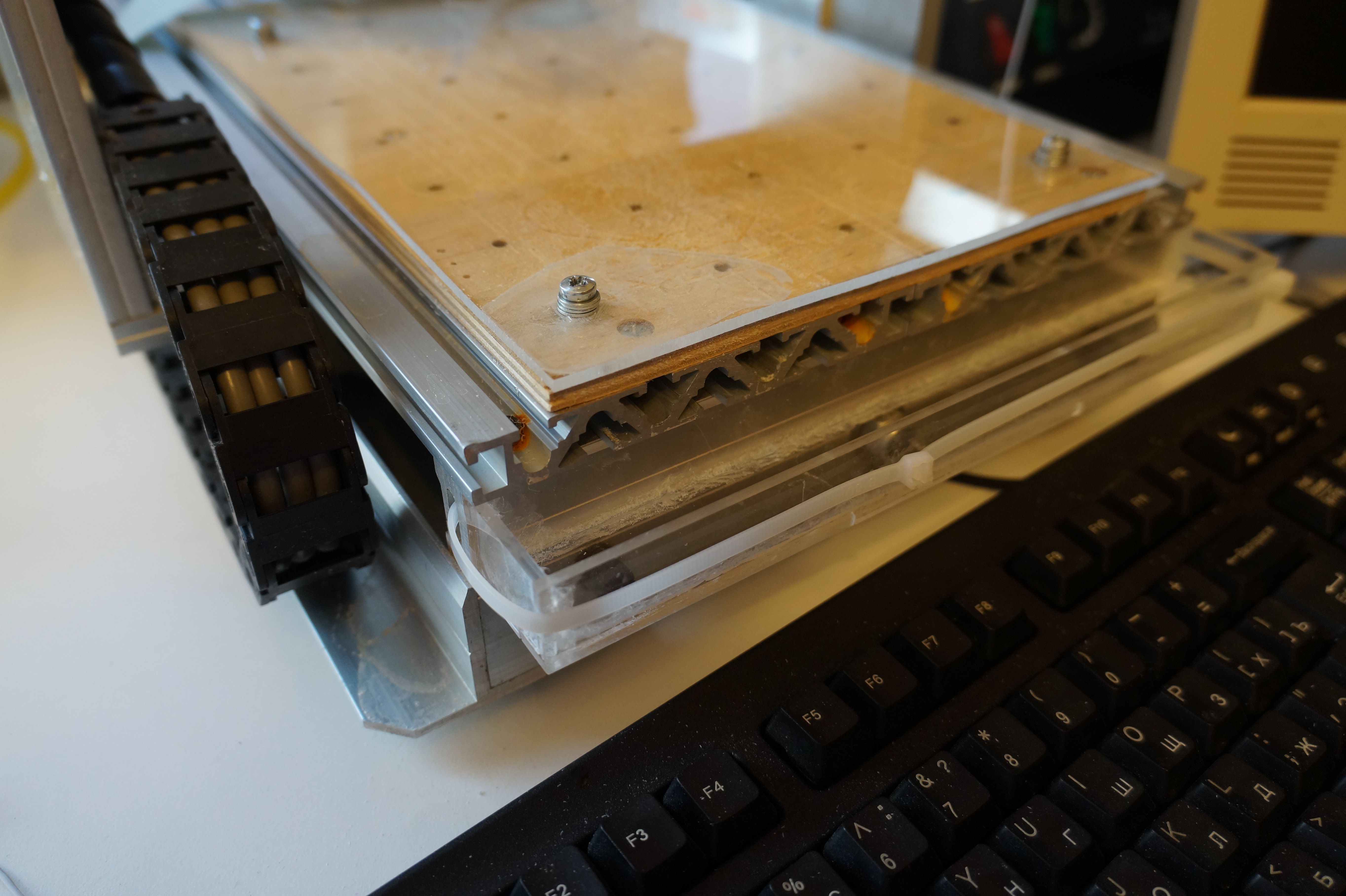
Table and water flow
The table has an interesting property that any liquid that you pour on it will pour out from the front (or back) slot openings, depending on the direction in which you tilt the machine, but practically no liquid will go elsewhere. This is the ground for the entire modification.
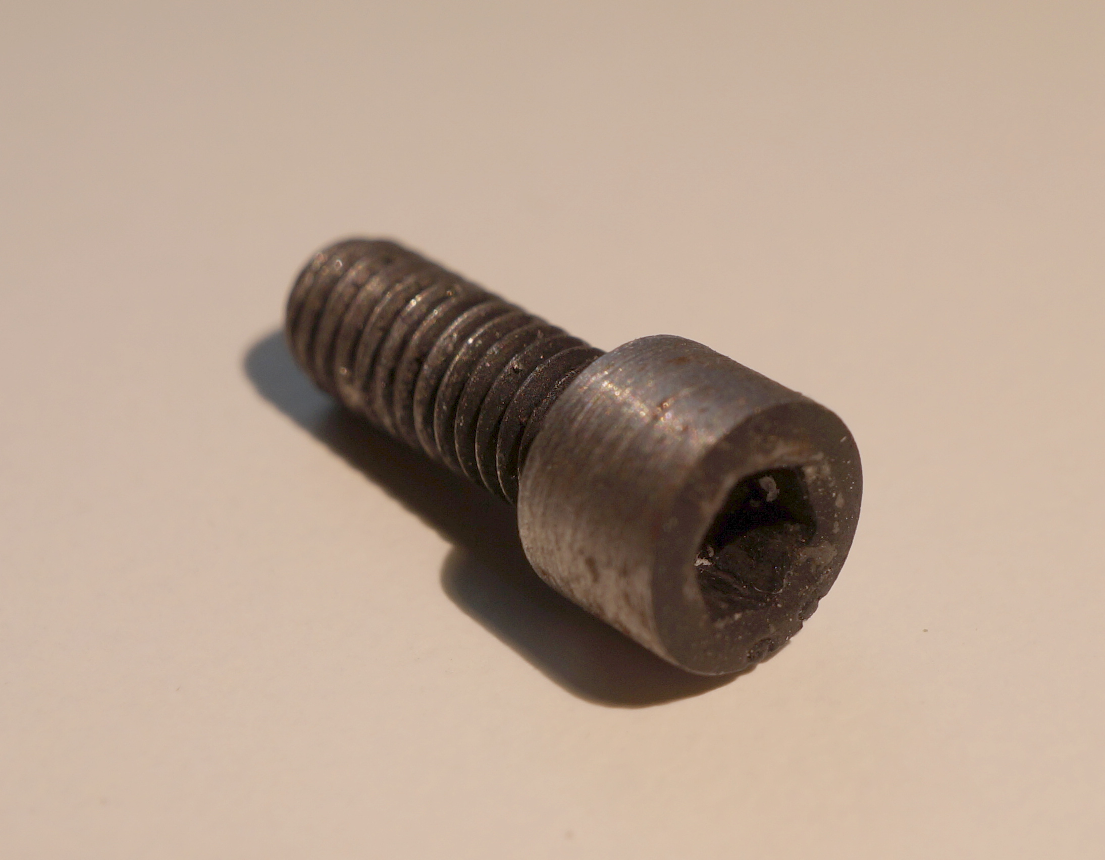
However, and this is important, the screws which attach the table of the mill to the rest of the frame rust very easily. You need to replace it with the same M4x10 hex cap screw, but made out of stainless steel. (While the contact of aluminium and stainless steel can produce galvanic corrosion in some circumstances, in this case it shouldn’t happen over any interesting timeframe.)
Designing control board
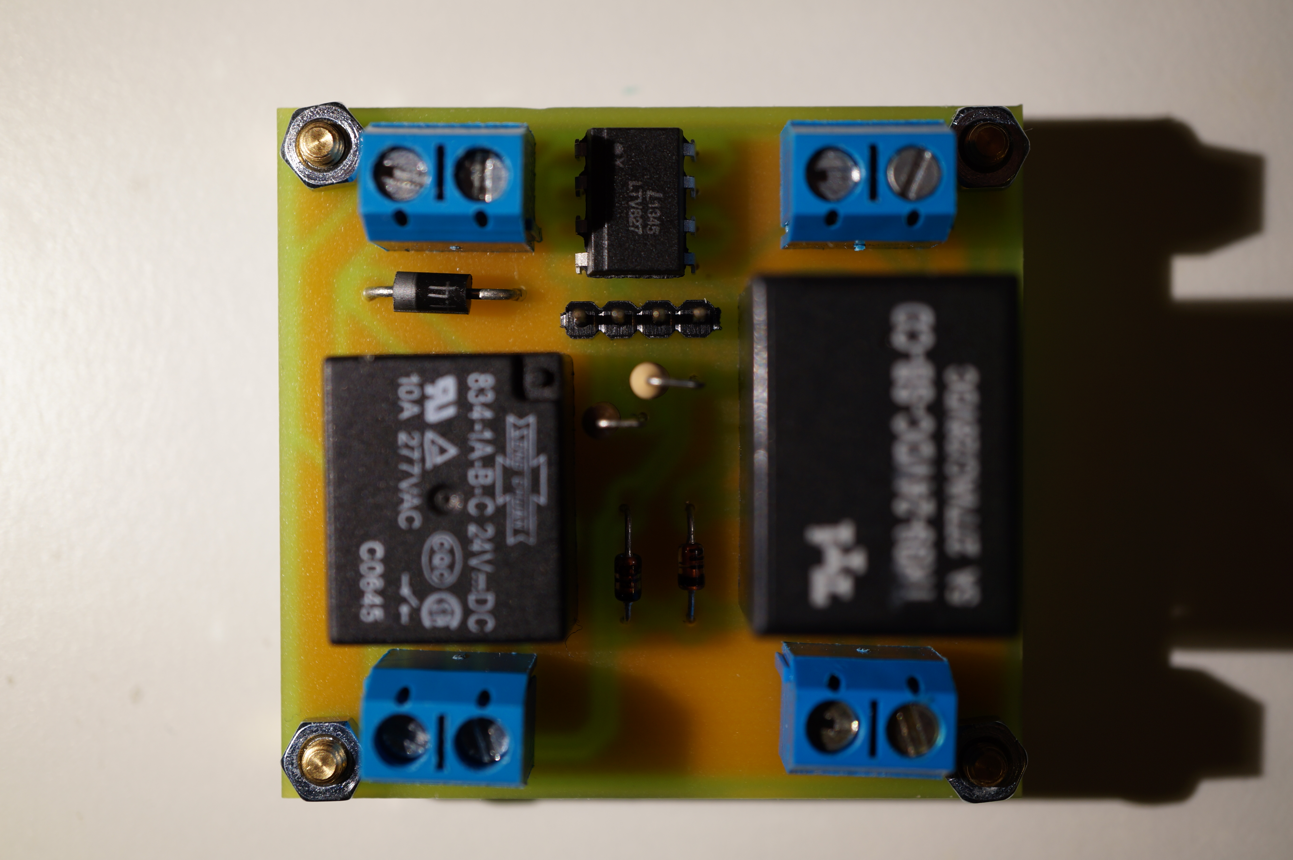
I have designed the modification around adding two PCBs to the control block; one with the factory-made buck converter for the pump, and another to integrate it with the LPT interface board. I decided that it is easiest to use relays for switching powerful inductive loads.
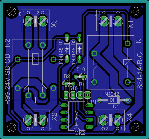
The integration board (EAGLE source) is a very simple board with two relays that is designed to be used with the LPT interface board.
Note that the board misses a connection between two parts of a ground polygon. You would probably want to fix that, so I don’t include production artifacts.
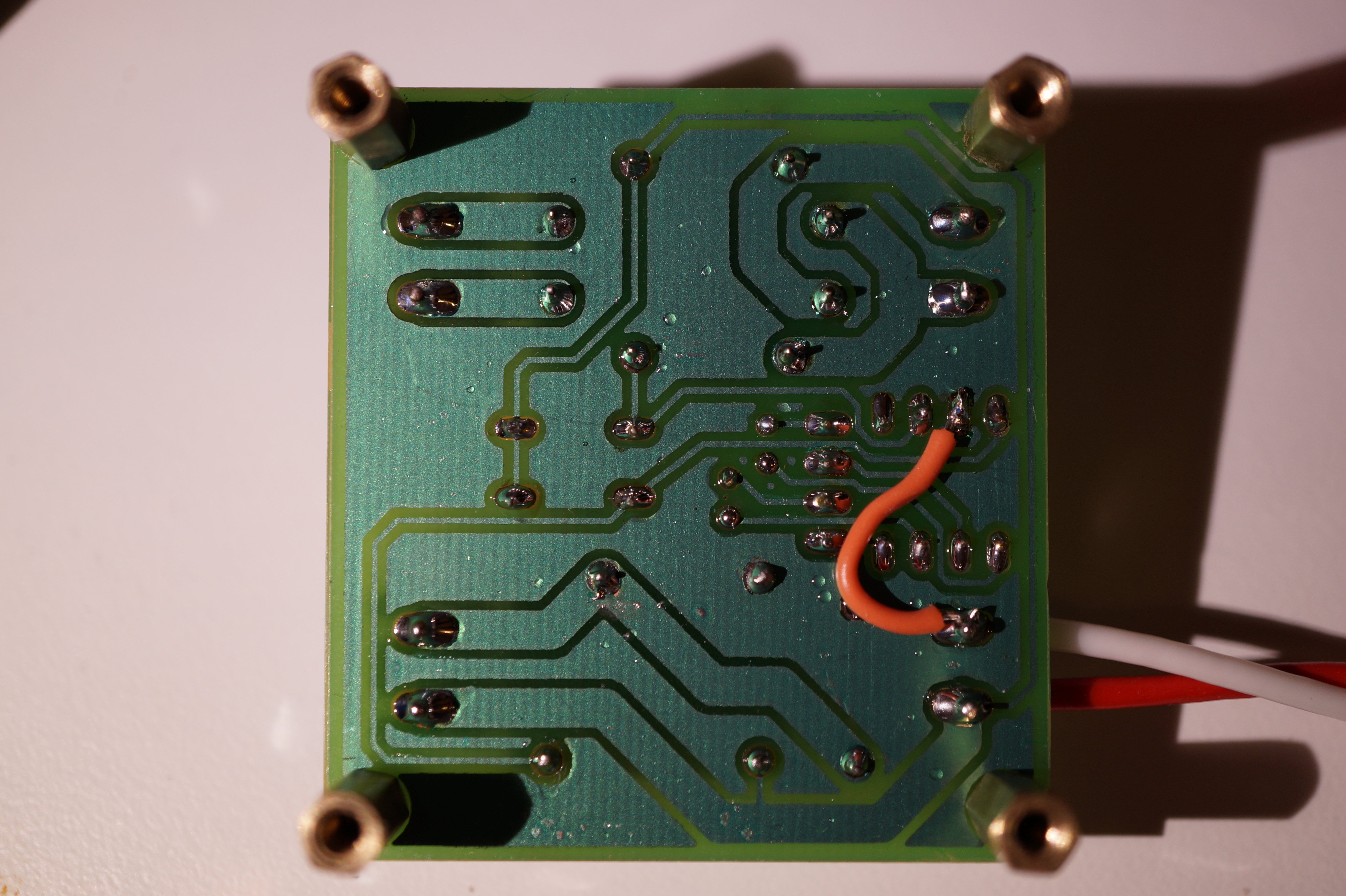
The board is manufactured as described in “Producing PCBs using photolithography”.
The board is connected as follows:
| Connector | Designation |
|---|---|
| X1 | buck converter IN |
| X2, X3 | splice into the spindle supply |
| X4 | 24V tap |
| JP1 | the CP-..DIR+ connector on LPT interface board |

Installing control board
The control board and the buck converter board are attached to the case using the screws and PCB stands. The case is drilled using a template, as described in the SMPS conversion note. The cord connected to the coolant pump is simply passed through a spare hole in the case, knotted inside to prevent an external force from pulling it out of the screw terminal on the PCB.
The EMC2 configuration described in earlier note already supports the newly added features.


")
