CNC3020T: EMC2 configuration and hidden features
Tags:CNC3020T only comes with a configuration for Mach3, a Windows CNC controller software I’m not really interested in. Additionally, for some weird reason, its control block requires you to adjust spindle speed manually with a potentiometer.
Fortunately, all of that can be fixed; moreover, the control block is much more powerful than it seems.
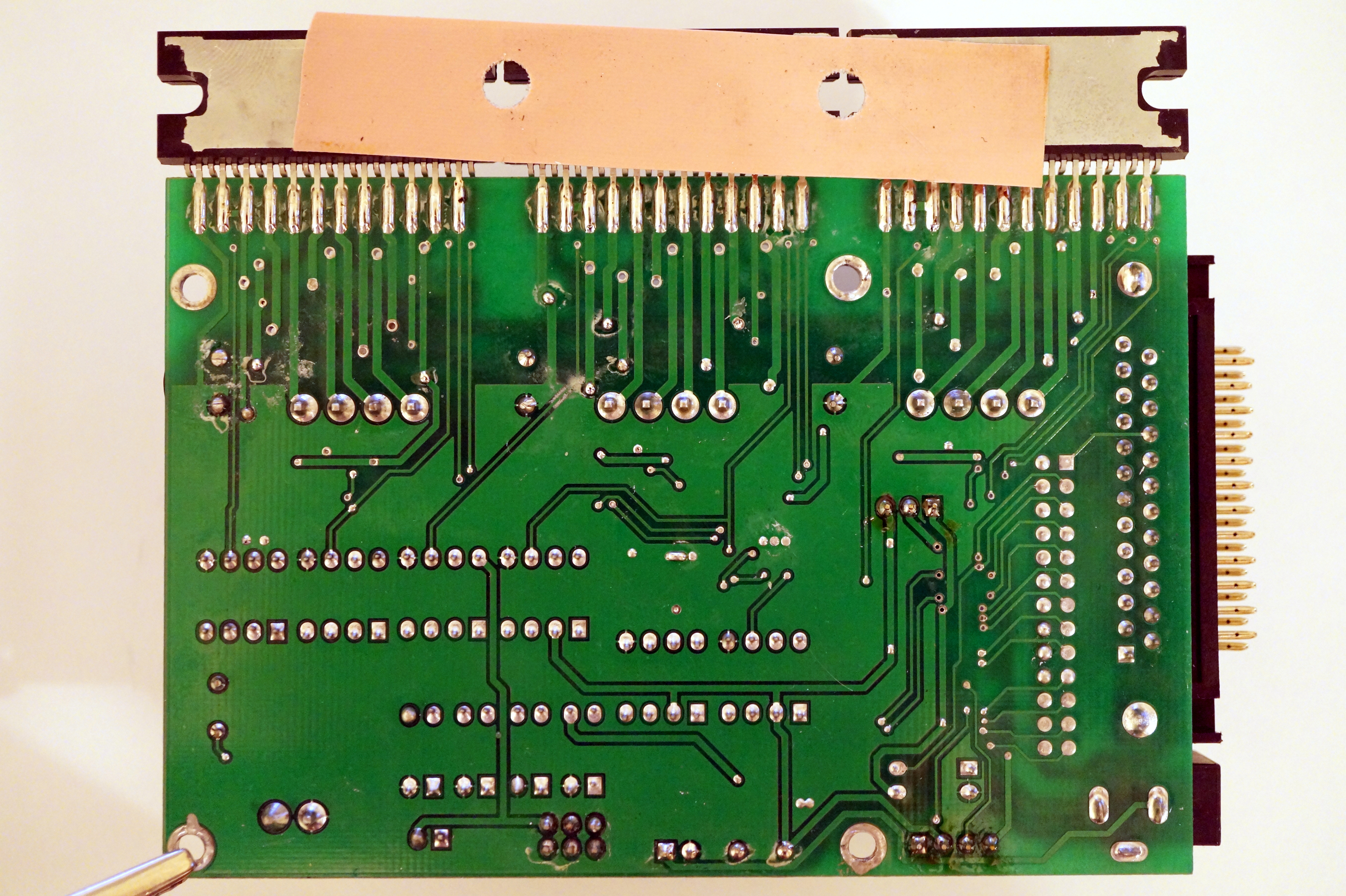
The stepper board looks like this:
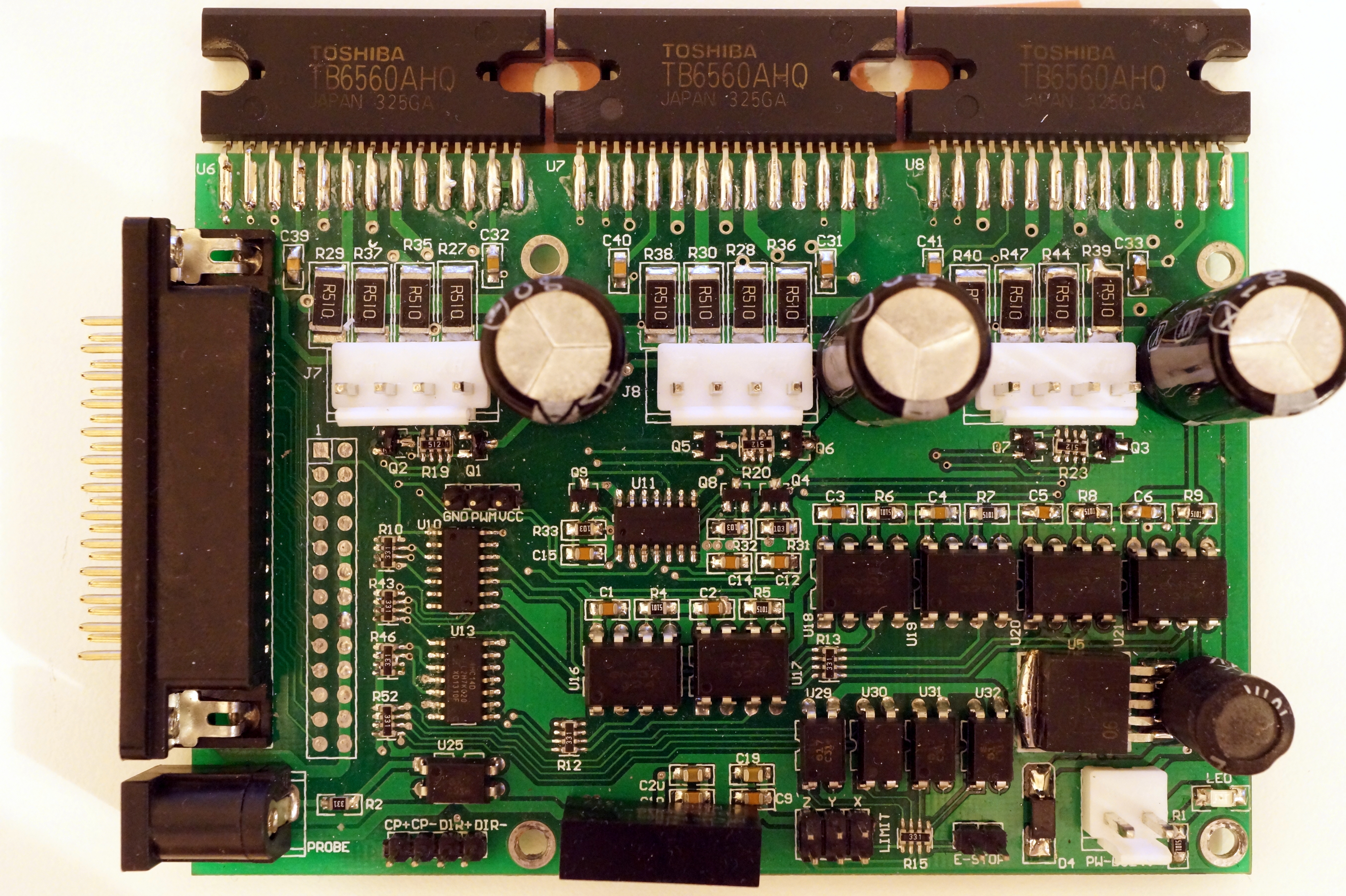
The connectors J7, J8, J9 correspond to axes X, Y, Z in that order.
IC part numbers and their functions:
| Component | Part # | Function |
|---|---|---|
| U5 | AP1501 | buck converter |
| U6-U8 | TB6560AHQ | stepping motor driver |
| U10, U11, U13 | 74HC140 | hex inverting Schmitt trigger |
| U16-U21 | 6N137 | optocoupler |
| U25, U29-U32 | EL817 | optocoupler |
| black box below | B0505LS | isolating DC-DC converter |
As it can be seen, the board features quite a bit of unused functionality—it has unpopulated connectors for limit switches and spindle PWM, direction and cooling pump control. (I’ve soldered pinheads to them already.)
I didn’t trace the board completely, but it is built out of identical blocks.
I’ve drawn its input and output circuits (GNDIO and VCCIO are provided by the
isolating DC-DC converter):


I’ve also mapped board functions to LPT pins:
| Pin # | Direction | Function |
|---|---|---|
| 2 | OUT | X Step |
| 3 | OUT | X Direction |
| 4 | OUT | Y Step |
| 5 | OUT | Y Direction |
| 6 | OUT | Z Step |
| 7 | OUT | Z Direction |
| 8 | OUT | Coolant Pump |
| 9 | OUT | Spindle Direction |
| 10 | IN | Z Limit |
| 11 | IN | Y Limit |
| 12 | IN | X Limit |
| 13 | IN | ESTOP |
| 15 | IN | Probe |
| 17 | OUT | Spindle PWM |
(“Coolant Pump” is marked on board as CP+/CP−, “Spindle Direction”
is DIR+/DIR−.)
Miscellaneous machine parameters, gleaned from the attached “documentation” (a set of Mach3 screenshots in very poor resolution black&white):
| Parameter | Value |
|---|---|
| Step Time/Space | 3000 ns |
| Direction Setup/Hold | 1000 ns |
| Steps per revolution | 400 |
| Driver microstepping | 2 |
| Leadscrew pitch | 2 mm/rev |
| Max. velocity X/Y | 33.3 mm/s |
| Max. acceleration X/Y | 200 mm/s² |
| Max. velocity Z | 11.7 mm/s |
| Max. acceleration Z | 100 mm/s² |
| Table travel X | 0..200 mm |
| Table travel Y | 0..300 mm |
| Table travel Z | −50..0mm |
All these parameters can be found in 3020T.stepconf, the source file for EMC2’s configuration wizard.
Now the funny thing is, the stepper control board has a PWM output, and the spindle control board has a PWM input:
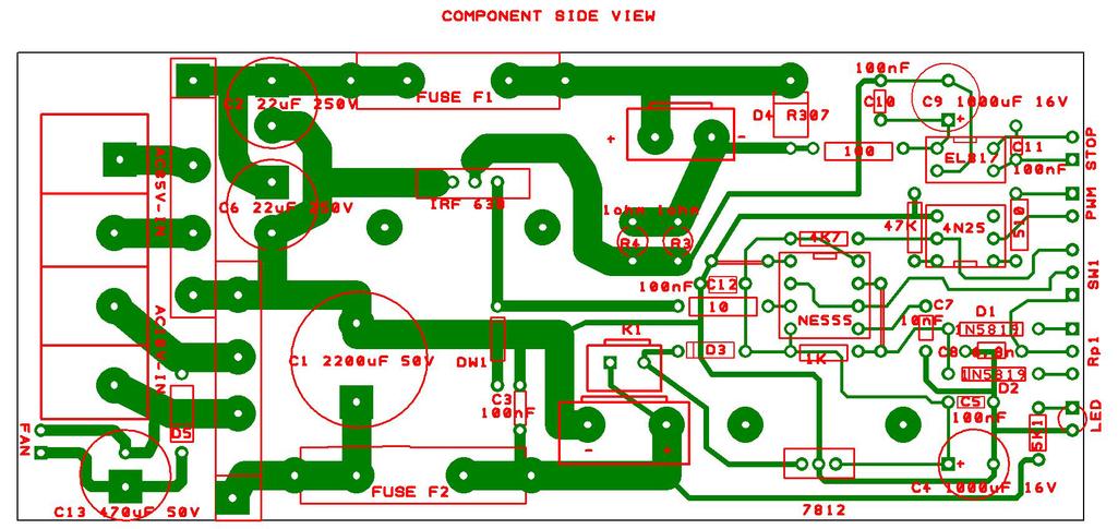
Pin 1 (rectangular) is positive, pin 2 is negative.
It would seem that obtaining software spindle speed control is as simple
as switching the SW1 switch to position 2 (jumper adjacent to PWM)
and connecting the boards with a pair of wires. And it totally works!
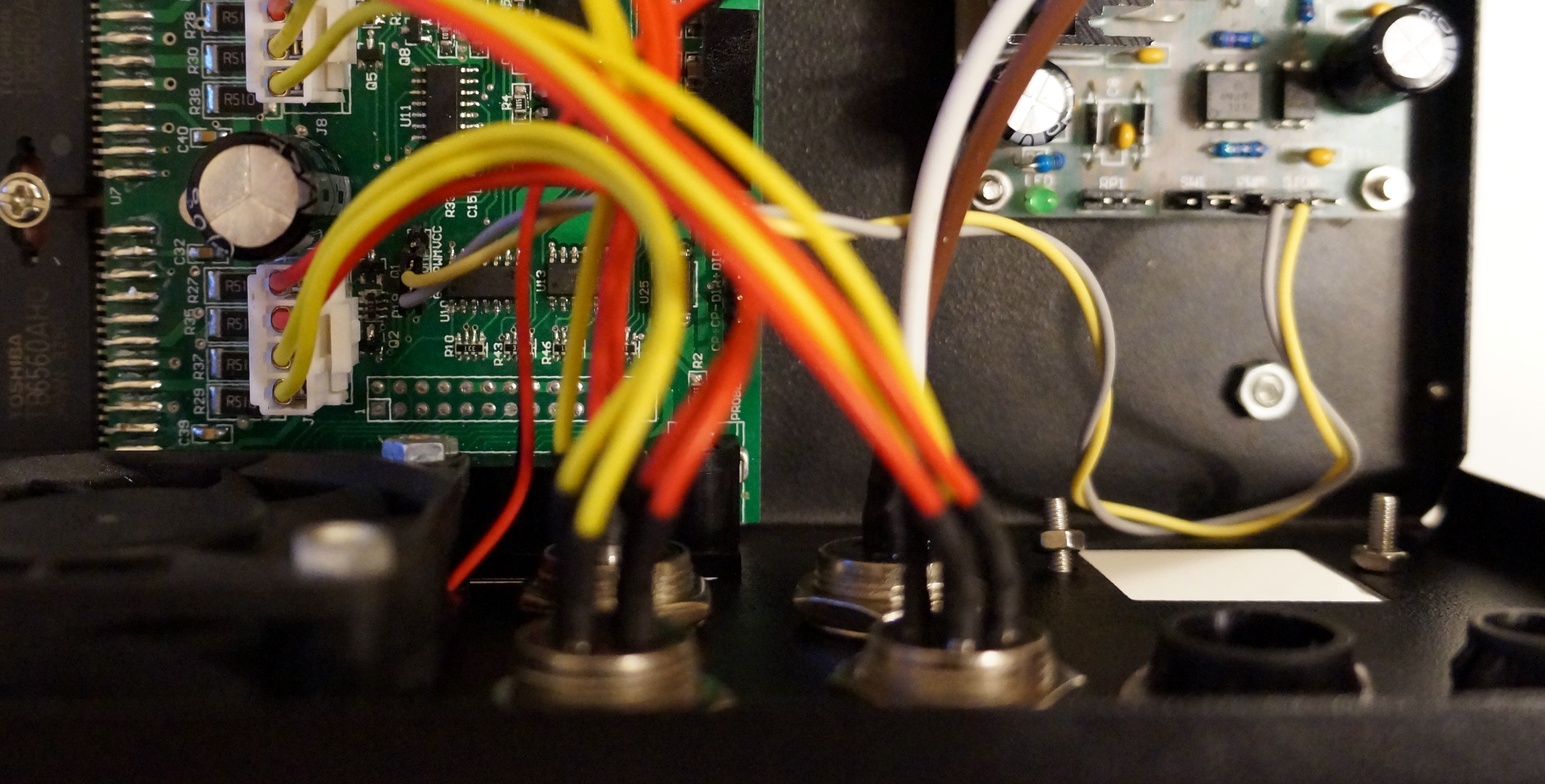
I have no idea why didn’t they provide it out of the box.