Making a lens using a CNC mill
Tags:Recently, I wondered if I could mill out a working lens using my CNC mill, for no other reason than curiosity. Turns out that yes, it is possible and even easy.
Tools
Materials
- 3mm thick clear cast acrylic sheet
- generic
- Two-component epoxy
- BISON
- Polishing paste, Cr₂O₆-based, grain size 7-1µm
- GOI #2
G-code
As usual, the G-code I publish is parametric; it can be easily customized for different material thickness, dimensions, etc, without the need for a proprietary CAM processor. Modify the “parameters” sections in the G-code and validate the result using OpenSCAM. The G-code will only work with LinuxCNC.
In this case, the G-code defines a three-part parabolic lens milled out of a material sheet #<_thickness> mm thick, defined by equation y = kx², with k = #<_scale>, using horizontal step #<_eps>.
1
2
3
4
5
6
7
8
9
10
11
12
13
14
15
16
17
18
19
20
21
22
23
24
25
26
27
28
29
30
31
32
33
34
35
36
37
38
39
40
41
42
43
44
45
46
47
48
49
50
51
52
53
54
55
56
57
58
59
60
61
62
63
64
65
66
67
68
69
70
71
72
73
74
75
76
77
78
79
80
81
82
83
84
85
86
87
88
89
90
91
92
93
94
95
96
97
98
99
100
101
102
103
104
105
106
107
108
109
110

; Mill out half-lens surface
O<half> sub
  #<rnow> = 0.01
  #<znow> = 0
  G0 X-#5410 Y0
  G0 Z0

  O100 while [#<znow> GE -[#<_thickness> - #<_edge_thick>]]
    G1 Z#<znow>

    G1 X[-#<rnow>]
    G2 I#<rnow>

    #<rnow> = [#<rnow> + #<_eps>]
    #<znow> = [-[#<_scale> * #<rnow> * #<rnow> ]]
  O100 endwhile

  G0 Z#<_zsafe>

O<half> endsub

; Cut-out
O<cutout> sub
  G0 X-#<_radius> Y0
  G0 Z0
  G1 Z-#<_thickness>
  G2 I#<_radius>
  G0 Z#<_zsafe>
O<cutout> endsub

; Mill out lens body
O<body> sub
  G0 X-#<_radius> Y0
  G0 Z0
  G2 I#<_radius> Z-#<_thickness> P[#<_thickness> / #<_step>]
  G2 I#<_radius>
  G0 Z#<_zsafe>
O<body> endsub

; Half-lens toplevel
O<halflens> sub
  M3
  F800
  O<half> call
  F400
  O<cutout>  call
  M5
O<halflens> endsub

; Lens body toplevel
O<lensbody> sub
  M3
  F400
  O<body> call
  M5
O<lensbody> endsub

; Offset G55 coordinate system based on G54
O<translate> sub
  #<dx> = #1
  #<dy> = #2

  G10 L2 P2 X[#5221 + #<dx>] Y[#5222 + #<dy>] Z#5223 R#5230

O<translate> endsub

; Metric, Absolute, XY plane
G21 G90 G17

; Safe Z level (above workpiece)
#<_zsafe>      = 25.

; Workpiece parameters
#<_thickness>  = 3.0  ; [mm] Full material thickness
#<_edge_thick> = 0.3  ; [mm] Thickness at edge
#<_step>       = 0.3  ; [mm] Helical milling step
#<offset>      = 5.0  ; [mm] Offset between different parts

; Lens parameters
#<_eps>        = 0.05 ; [mm] Horizontal milling step
#<_scale>      = 0.01 ; y = #<_scale> * x^2

#<_radius>     = sqrt[[#<_thickness> - #<_edge_thick>] / #<_scale>]

; Initialize
G54
G0 X0 Y0 Z#<_zsafe>
G55

; 1mm cylindrical diamond-cut endmill
; Feeds/speeds for milling acrylic. Use flood coolant!
S7000 G43 T1 M6

; First half-lens
O<translate> call [0] [-[2 * #<_radius> + #<offset>]]
O<halflens>  call

; Lens body
O<translate> call [0] [0]
O<lensbody>  call

; Second half-lens
O<translate> call [0] [2 * #<_radius> + #<offset>]
O<halflens>  call

; Finalize
G54
G0 Z#<_zsafe>

M2
Visualization (look at the funky glitch!):
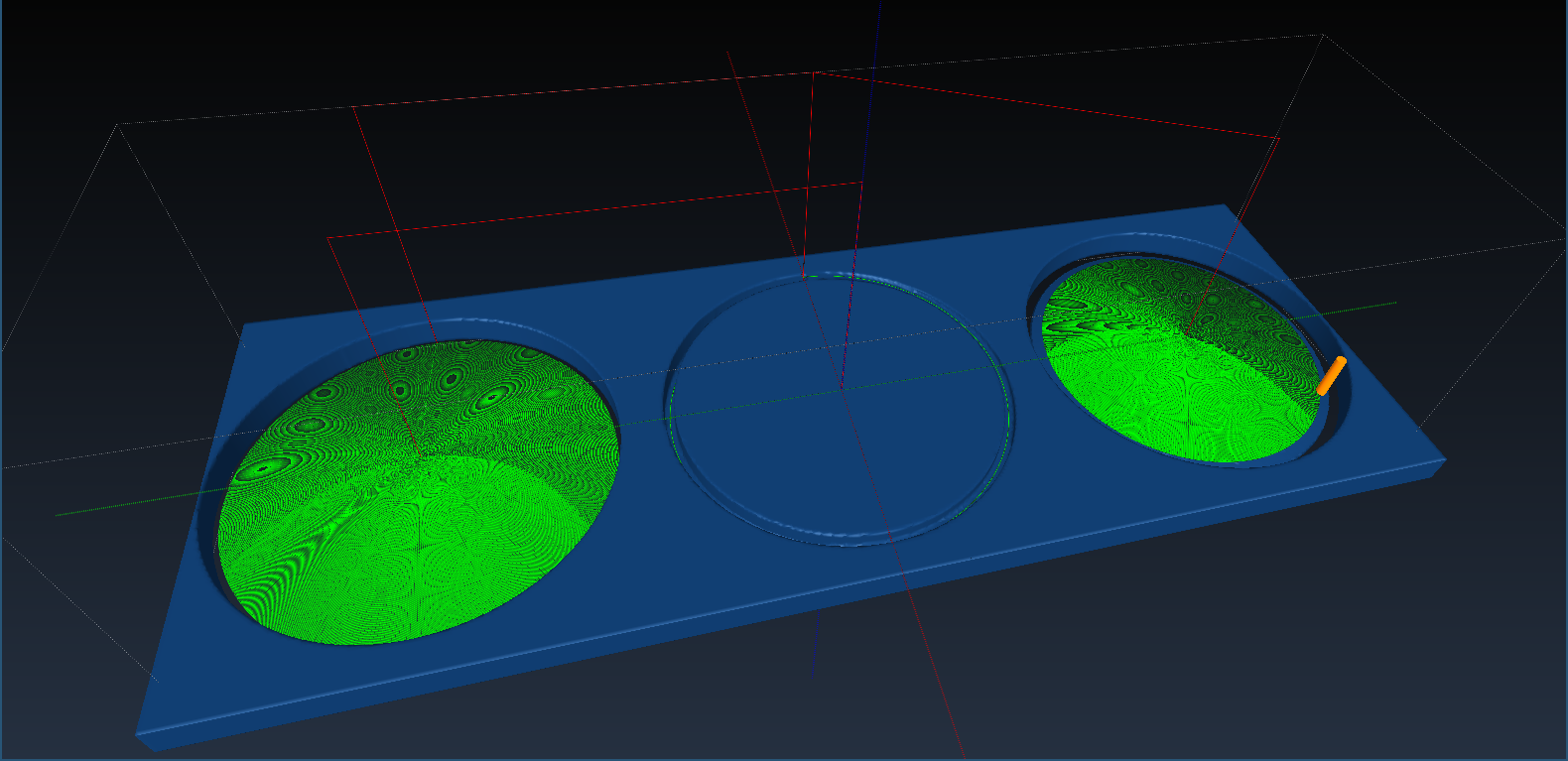
The default parameters above result in a lens 32.9mm in diameter, milled in steps of 50µm.
Milling
For milling acrylic successfully, I have found that flood coolant is indispensable. Without a decent amount of water cooling the workpiece, the surface is of horrible quality, and frequently the acrylic melts, spins on the endmill, solidifies on it and then promptly breaks the thin endmill with the lateral force.
As such, I now use a lot of coolant–about 1L of water per 5 minutes of work.
The resulting parts are very smooth to touch, but not transparent enough to form an image.


Gluing
I decided to glue the lens together before polishing it. I have applied a bit of epoxy on the central part, then squeezed the lens to push out air bubbles. It worked, however, there is a strange area of distortion near the center of the lens. I do not know why it appeared.


Polishing
Initially, I started to polish the lens by hand. However, I quickly became bored and decided to use a rotary tool instead. It worked marginally better, however, at one time I applied too much pressure and melted the acrylic.


Testing
And now the most exciting part–testing! Turns out the lens not only focuses light from a lamp to a point, but it also works, if very crudely, with my digital camera. Given that I did not give it any planning whatsoever, it’s nothing short of a miracle.


The poster on the photo:

Conclusions
Custom-made CNC-milled lenses are not complex to make; while the example above is not of high quality, it is my first attempt ever. I’m confident I could achieve much higher quality with the feedback I now have.
It is interesting to consider which hobby projects could be made much easier if one can manufacture custom aspherical optical elements.
It would make sense to change the process in some ways to get a better quality lens:
- Use thicker acrylic to avoid gluing anything, or at least glue several sheets prior to milling and mill out the parts which do not have glue-related defects.
- Use smaller milling step. 50µm is the vendor-provided repeated positioning resolution, but with microstepping, one could get resolutions as high as 10µm. It doesn’t have to be perfect, just reduce the amount of polishing work.
- Use a ballnose endmill, a cylindrical one isn’t suitable for profiling.
- Use a polishing paste that’s not from 80s, or at least properly dissolve it in kerosene. It’s a mess, though.