Ring oscillators on Silego GreenPAK 4
Tags:Silego GreenPAK 4 is a very nice programmable mixed-signal matrix that has a fully open-source toolchain consisting of Yosys and openfpga. In this note I look at fun and completely inappropriate uses of its logic primitives.
A ring oscillator consists of an odd number of inverters in a row:

It is, of course, unstable, and flips with a frequency that depends mostly on temperature and voltage, and the parameters of the circuit defined by the manufacturing process.
Ring oscillators are quite useful because they are small and self-contained. GreenPAK 4 already includes a ring oscillator primitive, GP_RINGOSC. Let’s take a look at its properties.
Tools
- GreenPAK4 Universal Developer Board
- Silego
- SLG46620V
- Silego
- iCE40HX8K-B-EVM
- Lattice Semi
- 1GSa/s 100MHz oscilloscope
- Rigol DS1104Z
GP_RINGOSC
The primitive is stated in the datasheet to oscillate at 27MHz. Let’s verify.
1
2
3
4
5
6
7

module top( (*LOC="P4"*) output q );
    GP_RINGOSC #(
        .AUTO_PWRDN(0)
    ) ringosc (
        .CLKOUT_FABRIC(q)
    );
endmodule
Build it the usual way:
1
2
3
4

$ yosys -p "read_verilog gp_ringosc.v" \
        -p "synth_greenpak4 -json gp_ringosc.json"
$ gp4par gp_ringosc.json -o gp_ringosc.txt
$ gp4prog -e gp_ringosc.json -v 3.3 -n 4
And take a look with the oscilloscope:
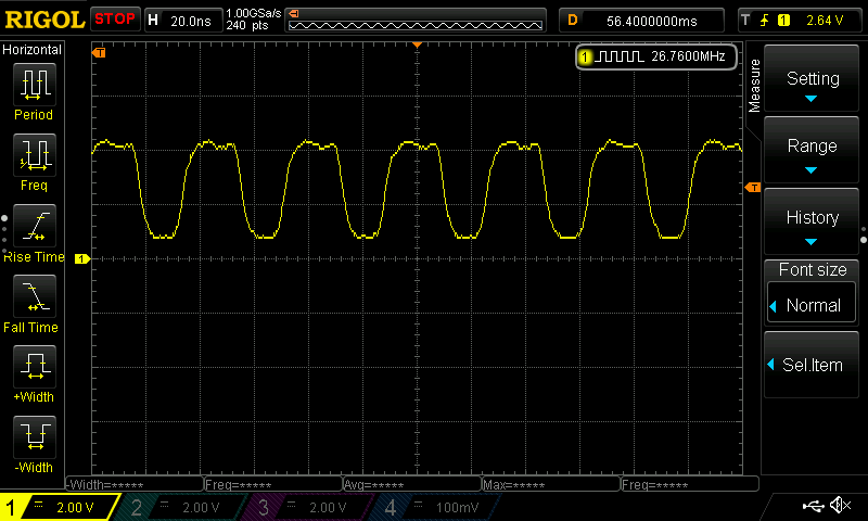
Note that I’m measuring it using the hardware frequency counter, not calculating it via the waveform shape, which would be far less precise.
Sure enough, 26.760MHz… or is it? While I was writing this part of the note, it drifted to 26.750MHz, and then after a while to 26.780MHz, and so on. Let’s look closer.
Frequency counter
There’s a fair amount of variability in the measured frequency, and also the oscilloscope doesn’t let me extract the pulse counter value via the network, so let’s use another FPGA (an iCE40-HX8K) as a frequency counter. It’s also supported by FOSS tooling, Yosys and arachne-pnr.
This is a fairly trivial design. It has a counter clocked directly by the device under test. Every 1s (according to the on-board crystal oscillator) the counter is gated for one system clock cycle, its value is read out and transmitted over UART. The readout strobe is only emitted every 12_000_001 system clock cycles to compensate for the readout lapse.
This design is good for input clocks up to just over 120MHz according to the timing estimate, with the critical path being the carrying through counter.
1
2
3
4
5
6
7
8
9
10
11
12
13
14
15
16
17
18
19
20
21
22
23
24
25
26
27
28
29
30
31
32
33
34
35
36
37
38
39
40
41
42
43
44
45
46
47
48
49
50
51
52
53
54
55
56
57
58
59
60
61
62
63
64
65
66
67
68
69
70
71
72
73
74
75
76
77
78
79
80
81
82
83
84

module FreqCounter(
        input  clk_12MHz,
        output uart_tx,
        input  clk_in,
        output clk_12MHz_tp,
        output uart_tx_tp,
    );

    // Test points
    assign clk_12MHz_tp = clk_12MHz;
    assign uart_tx_tp   = uart_tx;

    // Counter
    reg         active;
    wire        clk_gated = clk_in & active;
    reg  [31:0] counter;
    always @(posedge clk_gated)
        counter <= counter + 1;

    // Readout timer
    reg  [31:0] timeout;
    wire        timeout_strobe = (timeout == 0);
    always @(posedge clk_12MHz)
        if(timeout == 0)
            timeout <= 12_000_001;
        else
            timeout <= timeout - 1;

    // UART and readout FSM
    reg   [7:0] tx_data;
    reg         tx_ready;
    wire        tx_ack;
    UART #(
        .FREQ(12_000_000),
        .BAUD(115_200)
    ) uart (
        .reset(1'b1),
        .clk(clk_12MHz),
        .tx_o(uart_tx),
        .tx_data_i(tx_data),
        .tx_ready_i(tx_ready),
        .tx_ack_o(tx_ack)
    );

    localparam S_IDLE  = 0;
    localparam S_SYNC  = 1;
    localparam S_SEND  = 2;
    localparam S_WAIT  = 3;

    reg   [3:0] state  = S_IDLE;
    reg   [1:0] byteno = 2'd0;
    reg  [31:0] buffer;
    always @(posedge clk_12MHz)
        case(state)
            S_IDLE: begin
                if(timeout_strobe) begin
                    active <= 0;
                    state <= S_SYNC;
                end
            end
            S_SYNC: begin
                buffer <= counter;
                active <= 1;
                state <= S_SEND;
            end
            S_SEND: begin
                tx_data <= buffer >> (byteno * 8);
                tx_ready <= 1;
                if(!tx_ack)
                    state <= S_WAIT;
            end
            S_WAIT: begin
                tx_ready <= 0;
                if(tx_ack) begin
                    byteno <= byteno + 1;
                    if(byteno == 3)
                        state <= S_IDLE;
                    else
                        state <= S_SEND;
                end
            end
        endcase

endmodule
See the complete archive for the rest of the design. ./build.sh builds and uploads the gateware, and ./measure.rb /dev/ttyUSB1 reads out the frequency.
The clk_12MHz_tp test point is intended for measuring the on-board oscillator frequency. My oscilloscope indicates that it’s 12.0004 MHz, with no change over 24 hours.
Ultimately, I decided not to correct for deviation from 12.000000 MHz, since my oscilloscope doesn’t make any claims about the trueness of its reference clock, nor do I care about trueness of my frequency measurements. On the other hand, both the scope and the on-board oscillator seem to be precise enough relative to the DUT, which is what I need.
Aside: UART is just a pipe, right?
I’ve spent a few hours figuring out why I had intermittent framing errors–some of the bytes would be skipped when reading seemingly at random. I hacked and slashed the gateware, thinking I screwed it up somewhere, because the UART is just a dumb pipe, right?
Well, no. Turns out (and by “turns out” I mean “discovered with sigrok”; see the ./debug.sh script) the skipped byte was always 0x13… also known as XOFF. Linux has software flow control enabled by default on all TTYs, and that makes the UART not agnostic to the binary data going through it. That was irritating.
Behavior of GP_RINGOSC
Quantifying noise
If we take a look at the raw measurements, it’s pretty clear that the frequency jumps around a lot:
1
2
3
4
5
6

26551364
26551969
26552620
26552038
26551789
26552254
Let’s get some more data!
1
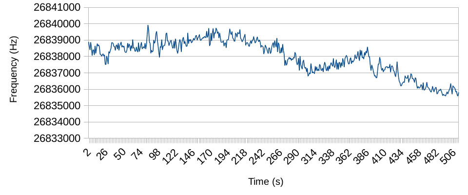
$ ./measure.rb | head -n512 >gp_ringosc-N512-3V3-29C.txt
There’s a lot of noise here:
Can we quantify this instability usefully, though? @bofh453 tells me I should use Allan deviation, which is designed exactly for this purpose. The implementation is simple enough:
1
2
3
4
5
6
7
8
9
10
11
12
13
14
15
16
17
18
19
20
21
22
23
24
25
26

#!/usr/bin/env ruby

class Array
  def mean; reduce(:+) / length; end
end

samples = File.read(ARGV[0]).split.map(&:to_f)
puts("n\t%d" % samples.count)

nominal_freq = samples.mean
puts("f\t%f" % nominal_freq)

puts("τ\tσ(τ)")
freq_diff =
  samples.map do |sample|
    sample / nominal_freq - 1
  end
(0..8).map { |n| 2**n }.each do |tau|
  variance =
    freq_diff
      .each_slice(tau).map { |slice| slice.mean }
      .each_cons(2).map do |y_n, y_np1|
        (y_np1 - y_n) ** 2
      end.mean / 2
  puts("#{tau}\t%.2g" % Math.sqrt(variance))
end
1
2
3

$ ./allan.rb freq-N512-3V3-29C.txt
n       512
f       26837964.519531
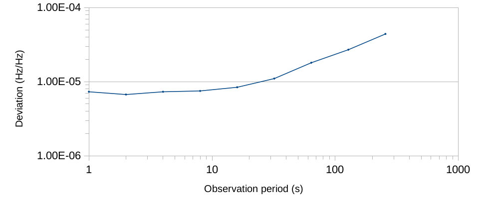
What does this plot indicate? Mostly the fact that the noise in GP_RINGOSC is a combination of pink noise (inherent in all semiconductors) and random walk noise (due to some environmental factor I can’t identify), as illustrated with the plot from the NIST website above:

Varying voltage
What’s the most obvious environmental factor? Voltage. Let’s see how the mean frequency changes if we sweep voltage. The sweep is from 3.3 V to 5.5 V only because the iCE40 developer board has all I/O banks at 3.3 V and anything less causes it to lose pulses… “are they 5V tolerant,” you ask? No, but I’ve realized that only after gathering the data. Ah well, didn’t seem to do it any harm.
1
2
3
4
5
6
7
8
9
10
11
12
13

#!/usr/bin/env ruby
require './measure'

class Array
  def mean; reduce(:+) / length; end
end

puts("Vcc\tfosc")
(33..55).map { |v| v/10.0 }.each do |vcc|
  system("gp4prog -q -v #{vcc}")
  freq = to_enum(:acquire).take(5).mean
  puts("#{vcc}\t#{freq}")
end
1
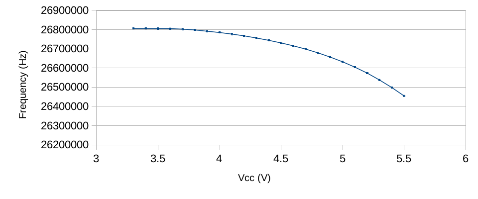
$ ./sweep_vcc.rb >gp_ringosc-3V3-to-5V5-29C.txt
The oscillator is more stable than I expected, deviating by less than 1.5% of its initial frequency over most of the operating range of SLG46620V (raw data):
Okay, what about the noise?
1
2
3
4
5
6

$ gp4prog -q -v 4.5
$ ./measure.rb | head -n512 >gp_ringosc-N512-4V5-29C.txt
$ ./allen.rb gp_ringosc-N512-4V5-29C.txt
$ gp4prog -q -v 5.4
$ ./measure.rb | head -n512 >gp_ringosc-N512-5V4-29C.txt
$ ./allen.rb gp_ringosc-N512-5V4-29C.txt
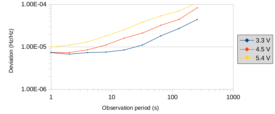
It seems to grow linearly with the supply voltage, with the random walk component, whatever it is, becoming more prominent (raw data: 3.3 V, 4.5 V, 5.4 V).
Rolling our own
Using specialized primitives is boring, let’s just make our own ring oscillator. There are two primitives in GreenPAK 4 that can be used for this: dedicated inverters and LUTs. Let’s see what properties they have and if they all work the same.
1
2
3
4

module top( (*LOC="P4"*) output q );
    (* LOC="INV_N" *) // replace N
    GP_INV inv(.IN(q), .OUT(q));
endmodule
1
2
3
4

module top( (*LOC="P4"*) output q );
    (* LOC="LUT2_N" *) // replace N
    GP_2LUT #(.INIT(4'b0001)) lut(.IN0(q), .OUT(q));
endmodule
1
2
3
4

module top( (*LOC="P4"*) output q );
    (* LOC="LUT3_N" *) // replace N
    GP_3LUT #(.INIT(4'b00000001)) lut(.IN0(q), .OUT(q));
endmodule
1
2
3
4

module top( (*LOC="P4"*) output q );
    (* LOC="LUT4_N" *) // replace N
    GP_4LUT #(.INIT(4'b0000000000000001)) lut(.IN0(q), .OUT(q));
endmodule
Frequency
First, let’s take a look at mean frequency at 5V supply voltage:
| Location | Matrix | Frequency (MHz) | Period (ns) |
|---|---|---|---|
| INV_0 | 0 | 125.3 | 7.98 |
| INV_1 | 1 | 121.3 | 8.24 |
| LUT2_0 | 0 | 108.7 | 9.20 |
| LUT2_1 | 0 | 108.5 | 9.22 |
| LUT2_2 | 0 | 108.5 | 9.22 |
| LUT2_4 | 1 | 109.7 | 9.12 |
| LUT2_5 | 1 | 110.3 | 9.07 |
| LUT3_0 | 0 | 102.4 | 9.77 |
| LUT3_8 | 1 | 103.1 | 9.70 |
| LUT4_0 | 0 | 69.1 | 14.5 |
| LUT4_1 | 1 | 89.7 | 11.1 |
Nothing surprising here–the larger the primitive, the slower it is; within the same matrix there is almost no difference; and the difference between different matrices is minor (LUT4_0 is an exception, as it is not identical to LUT4_1—it is a programmable function generator). I suspect that the difference between matrices is caused by the oscillator driving a longer net towards pin P4 (which is in matrix 0), so let’s verify that:
1
2
3
4

module top( (*LOC="P18"*) output q );
    (* LOC="INV_N" *) // replace N
    GP_INV inv(.IN(q), .OUT(q));
endmodule
| Location | Matrix | Frequency (MHz) | Period (ns) |
|---|---|---|---|
| INV_0 | 0 | 125.2 | 7.99 |
| INV_1 | 1 | 122 | 8.19 |
Well, apparently not.
In principle, connecting several LUTs in series should result in a total period as a sum of the parts. Let’s try that:
1
2
3
4
5
6
7
8
9

module top( (*LOC="P4"*) output q0 );
    wire q1, q2;
    (* LOC="LUT2_0" *)
    GP_2LUT #(.INIT(4'b0001)) lut1(.IN0(q0), .OUT(q1));
    (* LOC="LUT2_1" *)
    GP_2LUT #(.INIT(4'b0001)) lut2(.IN0(q1), .OUT(q2));
    (* LOC="LUT2_2" *)
    GP_2LUT #(.INIT(4'b0001)) lut3(.IN0(q2), .OUT(q0));
endmodule
In theory, this oscillator should have a frequency of 36.2 MHz at 5 V. In practice, it turns out to be… 112 MHz, which is higher than an individual GP_2LUT (bitstream for this circuit). Say what?! (Update: I figured it out)
What if we replace one of those with an inverter?
1
2
3
4
5
6
7
8
9

module top( (*LOC="P4"*) output q0 );
    wire q1, q2;
    (* LOC="LUT2_0" *)
    GP_2LUT #(.INIT(4'b0001)) lut1(.IN0(q0), .OUT(q1));
    (* LOC="LUT2_1" *)
    GP_2LUT #(.INIT(4'b0001)) lut2(.IN0(q1), .OUT(q2));
    (* LOC="INV_0" *)
    GP_INV inv(.IN(q2), .OUT(q0));
endmodule
This one should have a frequency of 37.9 MHz at 5 V, which is also exactly what I measure.
What if instead of an inverter we use a LUT from a different matrix?
1
2
3
4
5
6
7
8
9

module top( (*LOC="P4"*) output q0 );
    wire q1, q2;
    (* LOC="LUT2_0" *)
    GP_2LUT #(.INIT(4'b0001)) lut1(.IN0(q0), .OUT(q1));
    (* LOC="LUT2_1" *)
    GP_2LUT #(.INIT(4'b0001)) lut2(.IN0(q1), .OUT(q2));
    (* LOC="LUT2_4" *)
    GP_2LUT #(.INIT(4'b0001)) lut3(.IN0(q2), .OUT(q0));
endmodule
This circuit oscillates at 23.4 MHz. This is lower than the prediction of 36.2 MHz due to propagation delay through the cross-connection, which I won’t bother to measure, but it’s close enough.
I think that the 2LUT_0–2LUT_1–2LUT_2 cycle exhibits this behavior because of some resonance effect, since the self-oscillation frequencies are so close. I’m not sure how that works exactly, though.
Voltage
Something interesting I also noticed is the average voltage on the output pins; it differs far more than frequency. The supply voltage is 5V.
| Primitive | Output pin | Connection | Average voltage (V) |
|---|---|---|---|
| INV_1 | P4 | Cross | 1.97 |
| LUT2_4 | P4 | Cross | 2.55 |
| LUT3_8 | P4 | Cross | 2.32 |
| INV_0 | P18 | Cross | 2.35 |
| LUT2_0 | P18 | Cross | 2.60 |
| LUT3_0 | P18 | Cross | 2.79 |
| INV_0 | P4 | Direct | 2.80 |
| LUT2_0 | P4 | Direct | 2.78 |
| LUT3_0 | P4 | Direct | 2.84 |
| INV_1 | P18 | Direct | 3.07 |
| LUT2_4 | P18 | Direct | 3.21 |
| LUT3_8 | P18 | Direct | 3.11 |
Frequency drift
Let’s see how frequency changes with supply voltage:
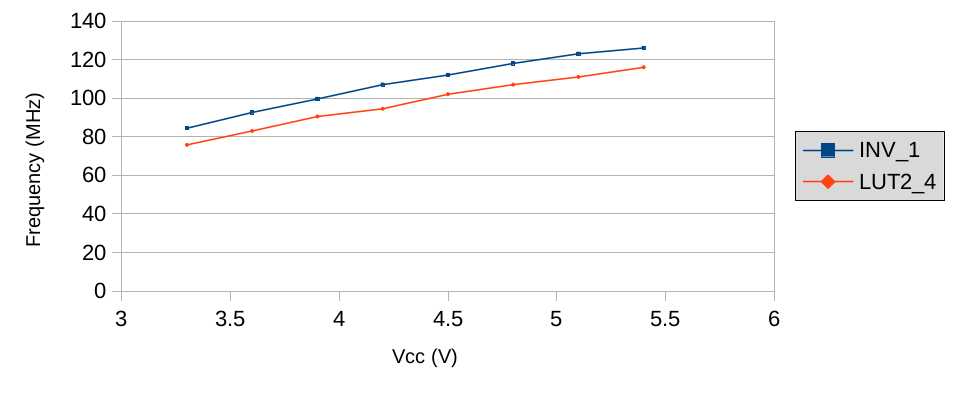
Not only these oscillators drift a lot more than GP_RINGOSC does, but also their frequency increases, whereas for GP_RINGOSC it decreases. Clearly the latter is compensated for supply voltage.
Noise
Now let’s compare all our oscillators: GP_RINGOSC, GP_INV, GP_2LUT and the 2LUT_0–2LUT_1–2LUT_4 ring, all at 5.4 V (raw data for INV_1, 2_LUT0, 2_LUT[014]):
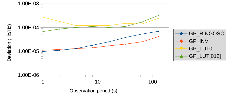
This is quite interesting. The amount of noise doesn’t depend on frequency. The single LUT and the three-LUT loop differ in frequency by a factor of 5 yet they have almost identical amount of noise. Otherwise, it seems that the more programmable logic is involed, the more noise this creates, but I’m not sure.
Results
To summarize:
- Ring oscillators can be constructed from programmable logic, and the highest frequency possible to achieve this way is ~130 MHz.
- Ring oscillators made from a single primitive drift with changing supply voltage by ~20 MHz/V;
GP_RINGOSCis compensated for that. - Ring oscillators made from programmable logic produce the same kind of noise as
GP_RINGOSC; noise is independent of frequency;GP_2LUTis an order of magnitude more noisy thanGP_INVorGP_RINGOSC. - The output of high-frequency ring oscillators made from programmable logic has a significant DC bias and they are probably not useful for much. Update: the Hacker News thread mentions that XOR between two ring oscillators could serve as a useful hardware random number generator.
- A loop of three closely located and matched LUTs configured as inverters oscillates at a frequency higher than individual LUTs for an unknown reason. Why? (Update: I figured it out)
I also now have a newfound appreciation of crystal oscillators.