Replacement for the Ricor K526S controller
Tags:I have a bunch of Ricor K526S cryocoolers. In this note I describe a controller replacement for one of them, which had the built-in controller die.
Interface
Electrically speaking, a K526S cryocooler is simply a BLDC motor with Hall sensors. It is very easy to drive one, and the most complicated part is determining the pinout. Here is the interposer board it has inside, labelled with pin numbers (that I’ve arbitrarily assigned):
The pinout is as follows (phases A, B, C are ordered clockwise, looking from the BLDC drive end):
| Pin # | Wire color | Function |
|---|---|---|
| 1 | (none) | BLDC drive supply |
| 2 | (none) | Spreading confusion* |
| 3 | Blue | Hall sensor supply |
| 4 | Yellow | Phase A |
| 5 | Orange | Phase C |
| 6 | Brown | Phase B |
| 7 | Green | Ground |
| U | Red | Phase A |
| V | White | Phase B |
| W | Black | Phase C |
* Not actually connected anywhere, but still runs across the board and through two vias for some reason.
It is not known what Hall sensors exactly are used, but they appear to be of the common type, compatible with e.g. US5881. They tolerate at least 5 V of supply voltage, and have an open-drain NMOS output.
Controller logic
The following Silego SLG46620V gateware, implemented based on Microchip AN587 can drive the cryocooler at its maximum speed for the supplied drive voltage:
1
2
3
4
5
6
7
8
9
10
11
12
13
14
15
16
17
18
19
20
21
22
23
24
25
26
27
28
29
30
31
32
33

module top(
        (* LOC="P3" *) output uh,
        (* LOC="P4" *) output ul,
        (* LOC="P5" *) output vh,
        (* LOC="P6" *) output vl,
        (* LOC="P7" *) output wh,
        (* LOC="P8" *) output wl,
        (* LOC="P14", PULLUP="10k" *) input us,
        (* LOC="P16", PULLUP="10k" *) input vs,
        (* LOC="P18", PULLUP="10k" *) input ws,
    );

    reg [5:0] drivers;
    always @(*) begin
        drivers <= 6'b000000;
        case({us, vs, ws})
            3'b101: drivers <= 6'b100100;
            3'b001: drivers <= 6'b000110;
            3'b011: drivers <= 6'b010010;
            3'b010: drivers <= 6'b011000;
            3'b110: drivers <= 6'b001001;
            3'b100: drivers <= 6'b100001;
        endcase
    end

    wire ui, vi, wi;
    assign {ui, ul, vi, vl, wi, wl} = drivers;

    // assign {uh, vh, wh} = ~{ui, vi, wi};
    assign {uh, vh} = ~{ui, vi};
    GP_2LUT #(.INIT(4'b0001)) lut (.IN0(wi), .OUT(wh));

endmodule
It can be built and run with:
1
2
3
4
5
6
7

#!/bin/sh -ex

yosys -q \
  -p "read_verilog -noautowire bldc.v" \
  -p "synth_greenpak4 -json bldc.json"
gp4par -q bldc.json -o bldc.txt
gp4prog -q -e bldc.txt -v 5 -n 1,3,4,5,6,7,8,14,16,18
The connections from the SLG46620V to the MOSFETs and sensors are as follows:
| SLG46620V pin # | K526S connection |
|---|---|
| 3 | U high side driver |
| 4 | U low side driver |
| 5 | V high side driver |
| 6 | V low side driver |
| 7 | W high side driver |
| 8 | W low side driver |
| 14 | 4 |
| 16 | 6 |
| 18 | 5 |
| 1 (supply) | 3 |
| 11 (ground) | 7 |
When writing this note I’ve used Vishay Si4564DY MOSFETs, which seem to perform satisfactorily. At no load (with the crankshaft exposed to atmosphere) rotation accelerates until about 8 V, and after that point only current grows. Current under load is to be determined.
Phase order
There are three possible mappings of Hall sensor phases to coil phases. The rotor will spin regardless of how good the match is, as it has a fair amount of inertia (in fact, once spinning, it’ll keep spinning even if one of the coils is completely disconnected). Thus, it is not obvious what the correct mapping is. I’ve measured the natural frequency for all three combinations, at 8 V coil supply:
| Phase mapping | Period |
|---|---|
| A:4 B:6 C:5 | 19 ms |
| A:5 B:4 C:6 | 24 ms |
| A:6 B:5 C:4 | 19 ms |
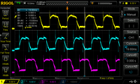
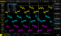
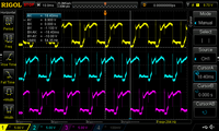
The waveforms measured at U, W, V differ considerably:
I’ve also tried stepping the coils using the following gateware:
1
2
3
4
5
6
7
8
9
10
11
12
13
14
15
16
17
18
19
20
21
22
23
24
25
26
27
28
29
30
31
32
33
34
35
36
37
38
39
40
41
42
43
44
45
46
47
48
49

module top(
        (* LOC="P3" *) output uh,
        (* LOC="P4" *) output ul,
        (* LOC="P5" *) output vh,
        (* LOC="P6" *) output vl,
        (* LOC="P7" *) output wh,
        (* LOC="P8" *) output wl,
        (* LOC="P14", PULLUP="10k" *) input us,
        (* LOC="P16", PULLUP="10k" *) input vs,
        (* LOC="P18", PULLUP="10k" *) input ws,
    );

    wire clk;
    GP_LFOSC #(
        .AUTO_PWRDN(0)
    ) lfosc (
        .CLKOUT(clk)
    );

    localparam DIVIDER = 400;
    reg  [13:0] divcnt = DIVIDER;
    always @(posedge clk)
        if(divcnt == 0)
            divcnt <= DIVIDER;
        else
            divcnt <= divcnt - 1;

    wire stepclk = (divcnt == 0);

    reg [5:0] drivers;
    always @(posedge stepclk) begin
        case({us, vs, ws})
            3'b101: drivers <= 6'b100100;
            3'b001: drivers <= 6'b000110;
            3'b011: drivers <= 6'b010010;
            3'b010: drivers <= 6'b011000;
            3'b110: drivers <= 6'b001001;
            3'b100: drivers <= 6'b100001;
        endcase
    end

    wire ui, vi, wi;
    assign {ui, ul, vi, vl, wi, wl} = drivers;

    // assign {uh, vh, wh} = ~{ui, vi, wi};
    assign {uh, vh} = ~{ui, vi};
    GP_2LUT #(.INIT(4'b0001)) lut (.IN0(wi), .OUT(wh));

endmodule
The mapping A:4 B:6 C:5 runs the fastest, with the waveforms closest to a perfect sine, and steps without unexpected abrupt jumps, so it seems that it is the correct mapping.


