Implementing a UART in Verilog and Migen
Tags:In this note I’ll explore the differences between the HDLs Verilog and Migen.
Verilog code
A while ago, I wrote a simple UART in Verilog. It consists of three modules.
Clock divider
The first module defines a reusable clock divider that verifies that, given the input frequency, the requested frequency makes sense and (if specified) doesn’t deviate too much from the target:
1
2
3
4
5
6
7
8
9
10
11
12
13
14
15
16
17
18
19
20
21
22
23
24
25
26
27
28
29
30
31
32
33
34
35
36
37
38
39
40
41
42
43
44
45
46
47
48
49
50
51
52
53
54
55
56
57
58
59

/*
 * Static clock divider. Displays deviation from target output frequency during synthesis.
 *
 * Author: whitequark@whitequark.org (2016)
 *
 * Parameters:
 *  FREQ_I:  input frequency
 *  FREQ_O:  target output frequency
 *  PHASE:   polarity of the output clock after reset
 *  MAX_PPM: maximum frequency deviation; produces an error if not met
 *
 * Signals:
 *  reset:   active-low reset
 *  clk_i:   input clock
 *  clk_o:   output clock
 */
module ClockDiv #(
        parameter FREQ_I  = 2,
        parameter FREQ_O  = 1,
        parameter PHASE   = 1'b0,
        parameter MAX_PPM = 1_000_000
    ) (
        input  reset,
        input  clk_i,
        output clk_o
    );

    // This calculation always rounds frequency up.
    localparam INIT = FREQ_I / FREQ_O / 2 - 1;
    localparam ACTUAL_FREQ_O = FREQ_I / ((INIT + 1) * 2);
    localparam PPM = 64'd1_000_000 * (ACTUAL_FREQ_O - FREQ_O) / FREQ_O;
    initial $display({"ClockDiv #(.FREQ_I(%d), .FREQ_O(%d),\n",
                      "           .INIT(%d), .ACTUAL_FREQ_O(%d), .PPM(%d))"},
                     FREQ_I, FREQ_O, INIT, ACTUAL_FREQ_O, PPM);
    generate
        if(INIT < 0)
            _ERROR_FREQ_TOO_HIGH_ error();
        if(PPM > MAX_PPM)
            _ERROR_FREQ_DEVIATION_TOO_HIGH_ error();
    endgenerate

    reg [$clog2(INIT):0] cnt = 0;
    reg                  clk = PHASE;
    always @(posedge clk_i or negedge reset)
        if(!reset) begin
            cnt <= 0;
            clk <= PHASE;
        end else begin
            if(cnt == 0) begin
                clk <= ~clk;
                cnt <= INIT;
            end else begin
                cnt <= cnt - 1;
            end
        end

    assign clk_o = clk;

endmodule
It’s somewhat too complicated and inflexible due to my desire to have 50% duty cycle on something
that’s marked as “clock” going out of a reusable module. The error reporting is also quite
inelegant due to my toolchain, Icarus Verilog and Yosys, which did not leave me a better
way to report such errors that worked in both of them, and I did not want to litter code with
`ifdefs.
UART
The second one implements the UART itself, as well as its testbench:
1
2
3
4
5
6
7
8
9
10
11
12
13
14
15
16
17
18
19
20
21
22
23
24
25
26
27
28
29
30
31
32
33
34
35
36
37
38
39
40
41
42
43
44
45
46
47
48
49
50
51
52
53
54
55
56
57
58
59
60
61
62
63
64
65
66
67
68
69
70
71
72
73
74
75
76
77
78
79
80
81
82
83
84
85
86
87
88
89
90
91
92
93
94
95
96
97
98
99
100
101
102
103
104
105
106
107
108
109
110
111
112
113
114
115
116
117
118
119
120
121
122
123
124
125
126
127
128
129
130
131
132
133
134
135
136
137
138
139
140
141
142
143
144
145
146
147
148
149
150
151
152
153
154
155
156
157
158
159
160
161
162
163
164
165
166
167
168
169
170
171
172
173
174
175
176
177
178
179
180
181
182
183
184
185
186
187
188
189
190
191
192
193
194
195
196
197
198
199
200
201
202
203
204
205
206
207
208
209
210
211
212
213
214
215
216
217
218
219
220
221
222
223
224
225
226
227
228
229
230
231
232
233
234
235
236
237
238
239
240
241
242
243
244
245
246
247
248
249
250
251
252
253
254
255
256
257
258
259
260
261
262
263
264
265
266
267
268
269
270
271
272
273
274
275
276
277
278
279
280
281
282
283
284
285
286
287
288
289
290
291
292
293
294
295
296
297
298
299
300
301
302
303
304
305
306
307
308
309
310
311
312
313
314
315
316
317
318
319
320
321
322
323
324
325
326
327
328
329

/*
 * UART transceiver. Only RXD/TXD lines and 8n1 mode is supported.
 *
 * Author: whitequark@whitequark.org (2016)
 *
 * Parameters:
 *  FREQ:       frequency of `clk`
 *  BAUD:       baud rate of serial line
 *
 * Common signals:
 *  reset:      active-low reset; only affects rx_ready_o, rx_error_o and tx_ack_o
 *  clk:        input clock, from which receiver and transmitter clocks are derived;
 *              all transitions happen on (posedge clk)
 *
 * Receiver signals:
 *  rx_i:       serial line input
 *  rx_data_o:  received octet, only valid while (rx_ack_i)
 *  rx_ready_o: whether rx_data_o contains a complete octet
 *  rx_ack_i:   clears rx_full_o and indicates that a new octet may be received
 *  rx_error_o: is asserted if a start bit arrives while (rx_full_o), or
 *              if a start bit is not followed with the stop bit at appropriate time
 *
 * Transmitter signals:
 *  tx_o:       serial line output
 *  tx_data_i:  octet to be sent, needs to be valid while (tx_ready_i && !tx_ack_o)
 *  tx_ready_i: indicates that a new octet should be sent
 *  tx_ack_o:   indicates that an octet is being sent
 *  tx_empty_o: indicates that a new octet may be sent
 */
module UART #(
        parameter FREQ  = 1_000_000,
        parameter BAUD  = 9600
    ) (
        input           reset,
        input           clk,
        // Receiver half
        input           rx_i,
        output [7:0]    rx_data_o,
        output          rx_ready_o,
        input           rx_ack_i,
        output          rx_error_o,
        // Transmitter half
        output          tx_o,
        input  [7:0]    tx_data_i,
        input           tx_ready_i,
        output          tx_ack_o
    );

    // RX oversampler
    reg        rx_sampler_reset = 1'b0;
    wire       rx_sampler_clk;
    ClockDiv #(
        .FREQ_I(FREQ),
        .FREQ_O(BAUD * 3),
        .PHASE(1'b1),
        .MAX_PPM(50_000)
    ) rx_sampler_clk_div (
        .reset(rx_sampler_reset),
        .clk_i(clk),
        .clk_o(rx_sampler_clk)
    );

    reg  [2:0] rx_sample  = 3'b000;
    wire       rx_sample1 = (rx_sample == 3'b111 ||
                             rx_sample == 3'b110 ||
                             rx_sample == 3'b101 ||
                             rx_sample == 3'b011);
    always @(posedge rx_sampler_clk or negedge rx_sampler_reset)
        if(!rx_sampler_reset)
            rx_sample <= 3'b000;
        else
            rx_sample <= {rx_sample[1:0], rx_i};

    (* fsm_encoding="one-hot" *)
    reg  [1:0] rx_sampleno  = 2'd2;
    wire       rx_samplerdy = (rx_sampleno == 2'd2);
    always @(posedge rx_sampler_clk or negedge rx_sampler_reset)
        if(!rx_sampler_reset)
            rx_sampleno <= 2'd2;
        else case(rx_sampleno)
            2'd0: rx_sampleno <= 2'd1;
            2'd1: rx_sampleno <= 2'd2;
            2'd2: rx_sampleno <= 2'd0;
        endcase

    // RX strobe generator
    reg  [1:0] rx_strobereg = 2'b00;
    wire       rx_strobe    = (rx_strobereg == 2'b01);
    always @(posedge clk or negedge reset)
        if(!reset)
            rx_strobereg <= 2'b00;
        else
            rx_strobereg <= {rx_strobereg[0], rx_samplerdy};

    // RX state machine
    localparam RX_IDLE  = 3'd0,
               RX_START = 3'd1,
               RX_DATA  = 3'd2,
               RX_STOP  = 3'd3,
               RX_FULL  = 3'd4,
               RX_ERROR = 3'd5;
    reg  [2:0] rx_state = 3'd0;
    reg  [7:0] rx_data  = 8'b00000000;
    reg  [2:0] rx_bitno = 3'd0;
    always @(posedge clk or negedge reset)
        if(!reset) begin
            rx_sampler_reset <= 1'b0;
            rx_state <= RX_IDLE;
            rx_data <= 8'b00000000;
            rx_bitno <= 3'd0;
        end else case(rx_state)
            RX_IDLE:
                if(!rx_i) begin
                    rx_sampler_reset <= 1'b1;
                    rx_state <= RX_START;
                end
            RX_START:
                if(rx_strobe)
                    rx_state <= RX_DATA;
            RX_DATA:
                if(rx_strobe) begin
                    if(rx_bitno == 3'd7)
                        rx_state <= RX_STOP;
                    rx_data <= {rx_sample1, rx_data[7:1]};
                    rx_bitno <= rx_bitno + 3'd1;
                end
            RX_STOP:
                if(rx_strobe) begin
                    rx_sampler_reset <= 1'b0;
                    if(rx_sample1 == 1'b0)
                        rx_state <= RX_ERROR;
                    else
                        rx_state <= RX_FULL;
                end
            RX_FULL:
                if(rx_ack_i)
                    rx_state <= RX_IDLE;
                else if(!rx_i)
                    rx_state <= RX_ERROR;
        endcase

    assign rx_data_o  = rx_data;
    assign rx_ready_o = (rx_state == RX_FULL);
    assign rx_error_o = (rx_state == RX_ERROR);

    // TX sampler
    reg        tx_sampler_reset = 1'b0;
    wire       tx_sampler_clk;
    ClockDiv #(
        .FREQ_I(FREQ),
        // Make sure TX baud is exactly the same as RX baud, even after all the rounding that
        // might have happened inside rx_sampler_clk_div, by replicating it here.
        // Otherwise, anything that sends an octet every time it receives an octet will
        // eventually catch a frame error.
        .FREQ_O(FREQ / ((FREQ / (BAUD * 3) / 2) * 2) / 3),
        .PHASE(1'b0),
        .MAX_PPM(50_000)
    ) tx_sampler_clk_div (
        .reset(tx_sampler_reset),
        .clk_i(clk),
        .clk_o(tx_sampler_clk)
    );

    // TX strobe generator
    reg  [1:0] tx_strobereg = 2'b00;
    wire       tx_strobe    = (tx_strobereg == 2'b01);
    always @(posedge clk or negedge reset)
        if(!reset)
            tx_strobereg <= 2'b00;
        else
            tx_strobereg <= {tx_strobereg[0], tx_sampler_clk};

    // TX state machine
    localparam TX_IDLE  = 3'd0,
               TX_START = 3'd1,
               TX_DATA  = 3'd2,
               TX_STOP0 = 3'd3,
               TX_STOP1 = 3'd4;
    reg  [2:0] tx_state = 3'd0;
    reg  [7:0] tx_data  = 8'b00000000;
    reg  [2:0] tx_bitno = 3'd0;
    reg        tx_buf   = 1'b1;
    always @(posedge clk or negedge reset)
        if(!reset) begin
            tx_sampler_reset <= 1'b0;
            tx_state <= 3'd0;
            tx_data <= 8'b00000000;
            tx_bitno <= 3'd0;
            tx_buf <= 1'b1;
        end else case(tx_state)
            TX_IDLE:
                if(tx_ready_i) begin
                    tx_sampler_reset <= 1'b1;
                    tx_state <= TX_START;
                    tx_data <= tx_data_i;
                end
            TX_START:
                if(tx_strobe) begin
                    tx_state <= TX_DATA;
                    tx_buf <= 1'b0;
                end
            TX_DATA:
                if(tx_strobe) begin
                    if(tx_bitno == 3'd7)
                        tx_state <= TX_STOP0;
                    tx_data <= {1'b0, tx_data[7:1]};
                    tx_bitno <= tx_bitno + 3'd1;
                    tx_buf <= tx_data[0];
                end
            TX_STOP0:
                if(tx_strobe) begin
                    tx_state <= TX_STOP1;
                    tx_buf <= 1'b1;
                end
            TX_STOP1:
                if(tx_strobe) begin
                    tx_sampler_reset <= 1'b0;
                    tx_state <= TX_IDLE;
                end
        endcase

    assign tx_o       = tx_buf;
    assign tx_ack_o   = (tx_state == TX_IDLE);

endmodule

`ifdef TEST
`timescale 1us/1ns
`define f (1_000_000.0/1_000_000.0)
`define t (1_000_000.0/9600.0)
`define assert(x) if(!(x)) begin \
        $error("at %8t: assertion failed: (%s) = %b", $time, "x", x); \
        #100; \
        $finish_and_return(1); \
    end #0
module UARTTest();
    reg        baud_clk = 1'b0;
    always #(`t/2) baud_clk = ~baud_clk;

    reg        reset = 1'b0;
    reg        clk = 1'b0;
    always #(`f/2) clk = ~clk;

    reg        rx = 1'b1;
    wire [7:0] rx_data;
    wire       rx_ready;
    reg        rx_ack = 1'b0;
    wire       rx_error;
    wire       tx;
    reg  [7:0] tx_data;
    reg        tx_ready;
    wire       tx_ack;
    UART #(
        .FREQ(1_000_000)
    ) uart (
        .reset(reset),
        .clk(clk),
        .rx_i(rx),
        .rx_data_o(rx_data),
        .rx_ready_o(rx_ready),
        .rx_ack_i(rx_ack),
        .rx_error_o(rx_error),
        .tx_o(tx),
        .tx_data_i(tx_data),
        .tx_ready_i(tx_ready),
        .tx_ack_o(tx_ack)
    );

    initial begin
        $dumpfile("UARTTest.vcd");
        $dumpvars(0, UARTTest);

        #10 reset = 1;

        // RX tests
        `define B(v) rx = v; #`t;
        `define S    `B(0) `assert (rx_error === 0); `assert(rx_ready === 0);
        `define D(v) `B(v) `assert (rx_error === 0); `assert(rx_ready === 0);
        `define E    `B(1) `assert (rx_error === 0);
        `define A(v) #`t; `assert (rx_data === v); \
                     rx_ack = 1; while(rx_ready) #1; rx_ack = 0;
        `define F    #`t; `assert (rx_error === 1); \
                     rx = 1; reset = 0; while(rx_error) #1; reset = 1;

        // bit patterns
        #20 `S `D(1) `D(0) `D(1) `D(0) `D(1) `D(0) `D(1) `D(0) `E  `A(8'h55)
        #5  `S `D(1) `D(1) `D(0) `D(0) `D(0) `D(0) `D(1) `D(1) `E  `A(8'hC3)
        #30 `S `D(1) `D(0) `D(0) `D(0) `D(0) `D(0) `D(0) `D(1) `E  `A(8'h81)
        #3  `S `D(1) `D(0) `D(1) `D(0) `D(0) `D(1) `D(0) `D(1) `E  `A(8'hA5)
        #10 `S `D(1) `D(1) `D(1) `D(1) `D(1) `D(1) `D(1) `D(1) `E  `A(8'hFF)

        // framing error
        #5  `S `D(1) `D(1) `D(1) `D(1) `D(1) `D(1) `D(1) `D(1) `B(0) `F

        // overflow error
        #10 `S `D(1) `D(1) `D(1) `D(1) `D(1) `D(1) `D(1) `D(1) `E  `B(0) `F

        `undef B
        `undef S
        `undef D
        `undef E
        `undef A
        `undef F

        #10;

        // TX tests
        `define B(v) #`t; `assert (tx === v);
        `define S(v) `assert (tx === 1); `assert (tx_ack == 1); \
                     tx_data = v; tx_ready = 1; while(tx) #(`t/50); #(`t/2); tx_ready = 0; \
                     `assert (tx === 0); `assert (tx_ack == 0);
        `define D(v) `assert (tx_ack == 0); `B(v)
        `define E    `assert (tx_ack == 0); `B(1) \
                     `assert (tx_ack == 0); #100;

        `S(8'h55) `D(1) `D(0) `D(1) `D(0) `D(1) `D(0) `D(1) `D(0) `E
        `S(8'h81) `D(1) `D(0) `D(0) `D(0) `D(0) `D(0) `D(0) `D(1) `E
        `S(8'hFF) `D(1) `D(1) `D(1) `D(1) `D(1) `D(1) `D(1) `D(1) `E
        `S(8'h00) `D(0) `D(0) `D(0) `D(0) `D(0) `D(0) `D(0) `D(0) `E

        `undef B
        `undef S
        `undef E

        #100;
        $finish;
    end
endmodule
`endif
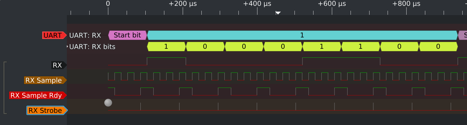
It’s, again, overcomplicated; my first design sampled the input at the end of every bit period, which of course made it unreliable. Instead of fixing that properly, i.e. sampling in the middle of the bit period, I remembered that I read about oversampling somewhere, and implemented that:
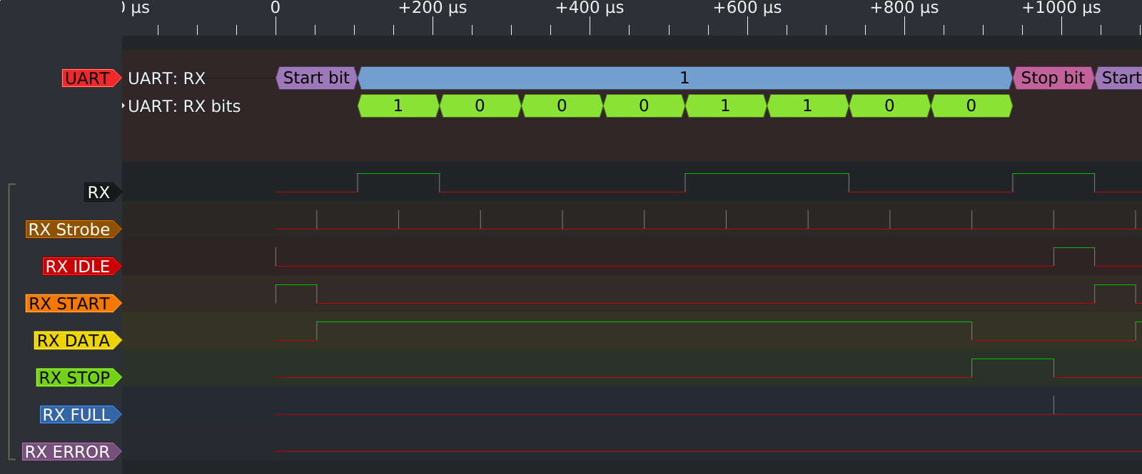
Notwithstanding that it’s still silly, it worked. This is what I should have done instead:
UART testbench
And a simple testbench design that implements a loopback using a single UART instance looks like this:
1
2
3
4
5
6
7
8
9
10
11
12
13
14
15
16
17
18
19
20
21
22
23
24
25
26
27
28
29
30
31
32
33
34
35
36
37
38
39
40
41
42
43
44
45
46
47
48
49
50
51
52
53
54
55

module UARTLoopback(
        input        clk_12mhz,
        output [7:0] leds,
        input        uart_rx,
        output       uart_tx,
        output       debug1,
        output       debug2
    );

    wire [7:0] rx_data;
    wire       rx_ready;
    wire       rx_ack;
    wire       rx_error;
    wire [7:0] tx_data;
    wire       tx_ready;
    wire       tx_ack;
    UART #(
        .FREQ(12_000_000),
        .BAUD(115200)
    ) uart (
        .reset(1'b1),
        .clk(clk_12mhz),
        .rx_i(uart_rx),
        .rx_data_o(rx_data),
        .rx_ready_o(rx_ready),
        .rx_ack_i(rx_ack),
        .rx_error_o(rx_error),
        .tx_o(uart_tx),
        .tx_data_i(tx_data),
        .tx_ready_i(tx_ready),
        .tx_ack_o(tx_ack)
    );

    reg        empty     = 1'b1;
    reg  [7:0] data      = 8'h00;
    wire       rx_strobe = (rx_ready && empty);
    wire       tx_strobe = (tx_ack && !empty);
    always @(posedge clk_12mhz) begin
        if(rx_strobe) begin
            data <= rx_data;
            empty <= 1'b0;
        end
        if(tx_strobe)
            empty <= 1'b1;
    end

    assign rx_ack   = rx_strobe;
    assign tx_data  = data;
    assign tx_ready = tx_strobe;

    assign leds = {rx_error, rx_data[6:0]};
    assign debug1 = uart_rx;
    assign debug2 = uart_tx;

endmodule
Migen code
The Migen implementation has everything in the same file: the UART, the verification code,
and the loopback testbench. (Even so, and even accounting for the fact that the Migen
implementation is simplified compared to the Verilog one, it is remarkably still smaller
than UART.v alone!)
1
2
3
4
5
6
7
8
9
10
11
12
13
14
15
16
17
18
19
20
21
22
23
24
25
26
27
28
29
30
31
32
33
34
35
36
37
38
39
40
41
42
43
44
45
46
47
48
49
50
51
52
53
54
55
56
57
58
59
60
61
62
63
64
65
66
67
68
69
70
71
72
73
74
75
76
77
78
79
80
81
82
83
84
85
86
87
88
89
90
91
92
93
94
95
96
97
98
99
100
101
102
103
104
105
106
107
108
109
110
111
112
113
114
115
116
117
118
119
120
121
122
123
124
125
126
127
128
129
130
131
132
133
134
135
136
137
138
139
140
141
142
143
144
145
146
147
148
149
150
151
152
153
154
155
156
157
158
159
160
161
162
163
164
165
166
167
168
169
170
171
172
173
174
175
176
177
178
179
180
181
182
183
184
185
186
187
188
189
190
191
192
193
194
195
196
197
198
199
200
201
202
203
204
205
206
207
208
209
210
211
212
213
214
215
216
217
218
219
220
221
222
223
224
225
226
227
228
229
230
231
232
233
234
235
236
237
238
239
240
241
242
243
244
245
246
247
248
249
250
251
252
253
254
255
256
257
258
259
260
261
262
263
264
265
266
267
268
269
270
271
272
273
274
275
276
277
278
279
280
281
282
283
284
285
286
287
288
289
290
291
292
293
294
295
296
297
298
299
300
301
302
303
304
305
306
307
308
309
310
311
312
313
314

from migen import *
from migen.genlib.fsm import *


def _divisor(freq_in, freq_out, max_ppm=None):
    divisor = freq_in // freq_out
    if divisor <= 0:
        raise ArgumentError("output frequency is too high")

    ppm = 1000000 * ((freq_in / divisor) - freq_out) / freq_out
    if max_ppm is not None and ppm > max_ppm:
        raise ArgumentError("output frequency deviation is too high")

    return divisor


class UART(Module):
    def __init__(self, serial, clk_freq, baud_rate):
        self.rx_data = Signal(8)
        self.rx_ready = Signal()
        self.rx_ack = Signal()
        self.rx_error = Signal()

        self.tx_data = Signal(8)
        self.tx_ready = Signal()
        self.tx_ack = Signal()

        divisor = _divisor(freq_in=clk_freq, freq_out=baud_rate, max_ppm=50000)

        ###

        rx_counter = Signal(max=divisor)
        self.rx_strobe = rx_strobe = Signal()
        self.comb += rx_strobe.eq(rx_counter == 0)
        self.sync += \
            If(rx_counter == 0,
                rx_counter.eq(divisor - 1)
            ).Else(
                rx_counter.eq(rx_counter - 1)
            )

        self.rx_bitno = rx_bitno = Signal(3)
        self.submodules.rx_fsm = FSM(reset_state="IDLE")
        self.rx_fsm.act("IDLE",
            If(~serial.rx,
                NextValue(rx_counter, divisor // 2),
                NextState("START")
            )
        )
        self.rx_fsm.act("START",
            If(rx_strobe,
                NextState("DATA")
            )
        )
        self.rx_fsm.act("DATA",
            If(rx_strobe,
                NextValue(self.rx_data, Cat(self.rx_data[1:8], serial.rx)),
                NextValue(rx_bitno, rx_bitno + 1),
                If(rx_bitno == 7,
                    NextState("STOP")
                )
            )
        )
        self.rx_fsm.act("STOP",
            If(rx_strobe,
                If(~serial.rx,
                    NextState("ERROR")
                ).Else(
                    NextState("FULL")
                )
            )
        )
        self.rx_fsm.act("FULL",
            self.rx_ready.eq(1),
            If(self.rx_ack,
                NextState("IDLE")
            ).Elif(~serial.rx,
                NextState("ERROR")
            )
        )
        self.rx_fsm.act("ERROR",
            self.rx_error.eq(1))

        ###

        tx_counter = Signal(max=divisor)
        self.tx_strobe = tx_strobe = Signal()
        self.comb += tx_strobe.eq(tx_counter == 0)
        self.sync += \
            If(tx_counter == 0,
                tx_counter.eq(divisor - 1)
            ).Else(
                tx_counter.eq(tx_counter - 1)
            )

        self.tx_bitno = tx_bitno = Signal(3)
        self.tx_latch = tx_latch = Signal(8)
        self.submodules.tx_fsm = FSM(reset_state="IDLE")
        self.tx_fsm.act("IDLE",
            self.tx_ack.eq(1),
            If(self.tx_ready,
                NextValue(tx_counter, divisor - 1),
                NextValue(tx_latch, self.tx_data),
                NextState("START")
            ).Else(
                NextValue(serial.tx, 1)
            )
        )
        self.tx_fsm.act("START",
            If(self.tx_strobe,
                NextValue(serial.tx, 0),
                NextState("DATA")
            )
        )
        self.tx_fsm.act("DATA",
            If(self.tx_strobe,
                NextValue(serial.tx, tx_latch[0]),
                NextValue(tx_latch, Cat(tx_latch[1:8], 0)),
                NextValue(tx_bitno, tx_bitno + 1),
                If(self.tx_bitno == 7,
                    NextState("STOP")
                )
            )
        )
        self.tx_fsm.act("STOP",
            If(self.tx_strobe,
                NextValue(serial.tx, 1),
                NextState("IDLE")
            )
        )


class _TestPads(Module):
    def __init__(self):
        self.rx = Signal(reset=1)
        self.tx = Signal()


def _test_rx(rx, dut):
    def T():
        yield; yield; yield; yield
    def B(bit):
        yield rx.eq(bit)
        yield from T()
    def S():
        yield from B(0)
        assert (yield dut.rx_error) == 0
        assert (yield dut.rx_ready) == 0
    def D(bit):
        yield from B(bit)
        assert (yield dut.rx_error) == 0
        assert (yield dut.rx_ready) == 0
    def E():
        yield from B(1)
        assert (yield dut.rx_error) == 0
    def O(bits):
        yield from S()
        for bit in bits:
            yield from D(bit)
        yield from E()

    def A(octet):
        yield from T()
        assert (yield dut.rx_data) == octet
        yield dut.rx_ack.eq(1)
        while (yield dut.rx_ready) == 1: yield
        yield dut.rx_ack.eq(0)
    def F():
        yield from T()
        assert (yield dut.rx_error) == 1
        yield rx.eq(1)
        yield dut.cd_sys.rst.eq(1)
        yield
        yield
        yield dut.cd_sys.rst.eq(0)
        yield
        yield
        assert (yield dut.rx_error) == 0

    # bit patterns
    yield from O([1, 0, 1, 0, 1, 0, 1, 0])
    yield from A(0x55)
    yield from O([1, 1, 0, 0, 0, 0, 1, 1])
    yield from A(0xC3)
    yield from O([1, 0, 0, 0, 0, 0, 0, 1])
    yield from A(0x81)
    yield from O([1, 0, 1, 0, 0, 1, 0, 1])
    yield from A(0xA5)
    yield from O([1, 1, 1, 1, 1, 1, 1, 1])
    yield from A(0xFF)

    # framing error
    yield from S()
    for bit in [1, 1, 1, 1, 1, 1, 1, 1]:
        yield from D(bit)
    yield from S()
    yield from F()

    # overflow error
    yield from O([1, 1, 1, 1, 1, 1, 1, 1])
    yield from B(0)
    yield from F()


def _test_tx(tx, dut):
    def Th():
        yield; yield
    def T():
        yield; yield; yield; yield
    def B(bit):
        yield from T()
        assert (yield tx) == bit
    def S(octet):
        assert (yield tx) == 1
        assert (yield dut.tx_ack) == 1
        yield dut.tx_data.eq(octet)
        yield dut.tx_ready.eq(1)
        while (yield tx) == 1: yield
        yield dut.tx_ready.eq(0)
        assert (yield tx) == 0
        assert (yield dut.tx_ack) == 0
        yield from Th()
    def D(bit):
        assert (yield dut.tx_ack) == 0
        yield from B(bit)
    def E():
        assert (yield dut.tx_ack) == 0
        yield from B(1)
        yield from Th()
    def O(octet, bits):
        yield from S(octet)
        for bit in bits:
            yield from D(bit)
        yield from E()

    yield from O(0x55, [1, 0, 1, 0, 1, 0, 1, 0])
    yield from O(0x81, [1, 0, 0, 0, 0, 0, 0, 1])
    yield from O(0xFF, [1, 1, 1, 1, 1, 1, 1, 1])
    yield from O(0x00, [0, 0, 0, 0, 0, 0, 0, 0])


def _test(tx, rx, dut):
    yield from _test_rx(rx, dut)
    yield from _test_tx(tx, dut)


class _LoopbackTest(Module):
    def __init__(self, platform):
        serial = plat.request("serial")
        leds   = Cat([plat.request("user_led") for _ in range(8)])
        debug  = plat.request("debug")

        self.submodules.uart = UART(serial, clk_freq=12000000, baud_rate=9600)

        empty = Signal(reset=1)
        data = Signal(8)
        rx_strobe = Signal()
        tx_strobe = Signal()
        self.comb += [
            rx_strobe.eq(self.uart.rx_ready & empty),
            tx_strobe.eq(self.uart.tx_ack & ~empty),
            self.uart.rx_ack.eq(rx_strobe),
            self.uart.tx_data.eq(data),
            self.uart.tx_ready.eq(tx_strobe)
        ]
        self.sync += [
            If(rx_strobe,
                data.eq(self.uart.rx_data),
                empty.eq(0)
            ),
            If(tx_strobe,
                empty.eq(1)
            )
        ]

        self.comb += [
            leds.eq(self.uart.rx_data),
            debug.eq(Cat(
                serial.rx,
                serial.tx,
                self.uart.rx_strobe,
                self.uart.tx_strobe,
                # self.uart.rx_fsm.ongoing("IDLE"),
                # self.uart.rx_fsm.ongoing("START"),
                # self.uart.rx_fsm.ongoing("DATA"),
                # self.uart.rx_fsm.ongoing("STOP"),
                # self.uart.rx_fsm.ongoing("FULL"),
                # self.uart.rx_fsm.ongoing("ERROR"),
                # self.uart.tx_fsm.ongoing("IDLE"),
                # self.uart.tx_fsm.ongoing("START"),
                # self.uart.tx_fsm.ongoing("DATA"),
                # self.uart.tx_fsm.ongoing("STOP"),
            ))
        ]


if __name__ == "__main__":
    import sys
    if sys.argv[1] == "sim":
        pads = _TestPads()
        dut = UART(pads, clk_freq=4800, baud_rate=1200)
        dut.clock_domains.cd_sys = ClockDomain("sys")
        run_simulation(dut, _test(pads.tx, pads.rx, dut), vcd_name="uart.vcd")
    elif sys.argv[1] == "loopback":
        from migen.build.generic_platform import *
        from migen.build.platforms import ice40_hx8k_b_evn

        plat = ice40_hx8k_b_evn.Platform()
        plat.add_extension([
            ("debug", 0, Pins("B16 C16 D16 E16 F16 G16 H16 G15"))
        ])

        plat.build(_LoopbackTest(plat))
        plat.create_programmer().load_bitstream("build/top.bin")
It can be simulated by running python3 UART.py sim, and loaded onto an iCE40-HX8K-B-EVN
developer board by running python3 UART.py loopback.
Migen vs Verilog
My impression of the migration is overwhelmingly positive. There wasn’t a single downside to it. I’ll list the benefits roughly in the decreasing order of importance.
No Verilog processes
In Verilog, any signal may be only driven from a single process, that is, an “always” block.
On the other hand, in Migen there is no such restriction; to drive a signal, a statement should
merely be in the same clock domain. (Statements are placed into a single always @(*) block and
an always @(posedge clk) block per clock domain during synthesis; Migen reset is synchronous.)
As a result, Migen doesn’t have this spurious coupling between syntax and behavior that
Verilog has; for example, instead of having a configurable phase like ClockDiv, the Migen
UART code simply resets the divider to the half of its wraparound value from one of
the FSM states, and this does not conflict with the decrement logic, as the later (in code)
action takes precedence.
In this example the counter is not factored out into a submodule, but putting it there would
not change anything as submodules are flattened.
When modeling logic, I try to do it elegantly; in Verilog this means writing an always
statement per an elementary component of the system, and factoring out reusable modules.
But the way processes are implemented places a restriction on the usefulness of such fine-grained
approach, and it significantly hinders my ability to model a system efficiently.
No FPGA initialization fiasco
In Verilog, there are three obvious ways to initialize registers: in an initial statement,
inline in the declaration, and using an explicit reset.
When designing FPGA gateware, the first two are preferable, since they use the FPGA’s ability to initialize registers when loading the bitstream, which results in less logic than when an explicit reset is used, and often the majority of registers will only be reset once. However, reusable modules ought to be resettable explicitly, and to accomodate that, the reset values have to be specified twice, which is error-prone, and forgetting it tends to create opaque bugs.
No wire/reg distinction
In Verilog, the distinction is useless since using a reg can be used to model both
combinatorial and sequential logic. Migen does away with the distinction; though so does
SystemVerilog, which has logic.
Native finite state machine support
In Verilog, you have to manually implement an FSM using localparam and case statements;
the compiler performs no next to no checking of validity, and the identifiers clash easily.
SystemVerilog improves on this somewhat with its typedef enum construct, but it’s still
not very ergonomic—surprising for such a common construct. It is also necessary to keep track
of the state register width manually.
In Migen, the built-in FSM module handles all that.
No instantiation boilerplate
In Verilog, instantiating modules with a large amount of inputs and outputs results in extreme
amounts of boilerplate: for every port, one a wire or reg declaration, one connection
in the instance, and often one assign statement connecting the signal elsewhere.
In Migen, clock and reset signals are connected implicitly, and modules are first-class, so they can be passed around and have their ports used directly. With less junk code comes less opportunity for copy-paste and other trivial errors.
First-class cosimulation
In Verilog, cosimulation requires integration with tool-specific interfaces that are generally awkward to use.
In Migen, cosimulation is a mere matter of writing a Python generator function, which can of course call arbitrary code that has a Python interface, such as a CPU simulator or even a driver for a developer board.
Platform resource management
In Verilog, toplevel ports are usually bound to specific pads or balls with an external constraint file, which usually does not provide any meaningful grouping and has to be written (or copied) per-project.
In Migen, toplevel ports are requested from the “platform”, which returns structured signals or groups of signals in response to a symbolic request; and the definitions can be composed, i.e. the set of signals can be initially defined by the base board, then extended by a per-project daughterboard, and so on.
Built-in build system
In Verilog, running a design on your hardware means awkwardly digging up that Makefile you first wrote five years ago and used ever since and updating it for your latest project, and maybe fixing a bug or two in your custom dependency management code.
In Migen, dependency management is provided by Python (which isn’t stellar but is far better), and going from HDL to a bitstream is a single function call.
Conclusions
Migen’s lack of restrictions around process and meaningful handling of resets has substantially helped me write good HDL. The rest are little increases in productivity that matter, especially together, but the lack of them is perhaps not a massive hindrance in Verilog.
I haven’t used Migen’s more advanced features yet, like parameterization of control flow, and especially arrays of signals indexed by signals; such arrays of signals in particular are not directly expressible in Verilog (though they seem to be possible in SystemVerilog) and so are likely to result in very obtuse code when implemented manually. But they are needed for the more complex logic, like bus arbiters, and I haven’t written one of those (yet).