CNC-milling glass
Tags:In an earlier note I described an improvised vacuum chamber. I wanted to perform sputtering in it, but an acrylic flange would melt if the feedthroughs got hot enough (and they will get hot), and that would be pretty gross.
In this note I describe how I CNC-milled a glass flange.
Tools
- CNC mill
- CNC3020T
- CNC3020T fixture attachment
- own work
- CNC3020T coolant mod
- own work
- flat endmill
- d=1.6mm two flute endmill
- diamond crown drill
- Dremel glass drilling bit 662
- diamond file set
- generic
Materials
- glass sheet
- bathroom mirror shelf, 12.5mm × 12.5mm × 3.9mm non-tempered soda glass panel
- acrylic sheet
- d=3mm
Milling fixture
The first step is to fabricate a fixture that would hold the glass. Other people have been using rather complicated fixtures, also made out of acrylic, but I decided to make a fixture that would only compensate for lateral load for simplicity. This has proved to be a good idea.
The following LinuxCNC G-code mills one half of the fixture suitable for my fixture attachment system, which uses a grid of M4 nuts spaced by 30mm:
1
2
3
4
5
6
7
8
9
10
11
12
13
14
15
16
17
18
19
20
21
22
23
24
25
26
27
28
29
30
31
32
33
34
35
36
37
38
39
40
41
42
43
44
45
46
47
48
49
50
51
52
53
54
55
56
57
58
59
60
61
62
63
64
65
66
67
68
69
70
71
72
73
74
75
76
77
78
79
80
81
82
83
84
85
86
87
88
89
90
91
92
93

( Helix-mill a hole. )
( Assumes metric, XY plane, feedrate, and tool compensation are set. )

O<helix_mill> sub
  #<xcenter> = #1 ( [mm] X center         )
  #<ycenter> = #2 ( [mm] Y center         )
  #<radius>  = #3 ( [mm] Hole radius      )
  #<zstart>  = #4 ( [mm] Z start position )
  #<zend>    = #5 ( [mm] Z end position   )

  G0 X[ #<xcenter> - #<radius> ] Y#<ycenter>

  G0 Z#<zstart>
  #<znow> = #<zstart>

  ( Mill out body with several full helical turns )
  O100 while [ #<znow> GT [ #<zend> + #<_zstep> ] ]

    #<znow> = [ #<znow> - #<_zstep> ]
    G2 I#<radius> J0 Z#<znow>

  O100 endwhile

  G2 I#<radius> J0 Z#<zend>

  ( Flat out the bottom )
  G2 I#<radius> J0

O<helix_mill> endsub

( --- BEGIN CONFIGURATION --- )

( 1.6mm cylindrical cutter )
T60 M6 S4000 F400

#<_zsafe>       = 10. ( Safe Z               [mm] )
#<_zstep>       = 1.  ( Pocketing Z step     [mm] )
#<_thickness>   = 3.  ( Acrylic thickness    [mm] )

( --- END CONFIGURATION --- )

( Metric, Absolute, XY plane )
G21 G90 G17

( Spindle on, Coolant on )
M3 M8

( Dwell for 2s )
G4 P2

G0 Z#<_zsafe>
G0 X0 Y0

( Holes )
G42
O<helix_mill> call [30.] [0.] [5.5 / 2] [0.] [-#<_thickness>]
G0 Z#<_zsafe>
O<helix_mill> call [0.] [0.] [5.5 / 2] [0.] [-#<_thickness>]
G0 Z#<_zsafe>
O<helix_mill> call [0.] [150.] [5.5 / 2] [0.] [-#<_thickness>]
G0 Z#<_zsafe>
O<helix_mill> call [30.] [150.] [5.5 / 2] [0.] [-#<_thickness>]
G40
G0 Z#<_zsafe>

( Outline )
O<outline> sub
  Z#1
  X-15 Y-15
       Y165
  X45
       Y135
  X15
       Y[135 - 125 + 0.9] ; glass edge size, corrected for mill error
  X45
       Y-15
  X-15
O<outline> endsub

#<znow> = -#<_zstep>
G41
G0 X-15 Y[-15 - #5410]
G1
O100 while [ #<znow> GT -#<_thickness> ]
  O<outline> call [#<znow>]
  #<znow> = [ #<znow> - #<_zstep> ]
O100 endwhile
O<outline> call [-#<_thickness>]

G40
G0 Z#<_zsafe>

M2
Unfortunately the G-code is not parametric and will have to be manually adjusted for particular application.
The G-code also contains correction for a positioning error, the reason for which I do not yet know: all distances were uniformly expanded at about 0.2mm per 30mm. The only edge that requires such precision was manually adjusted to compensate.
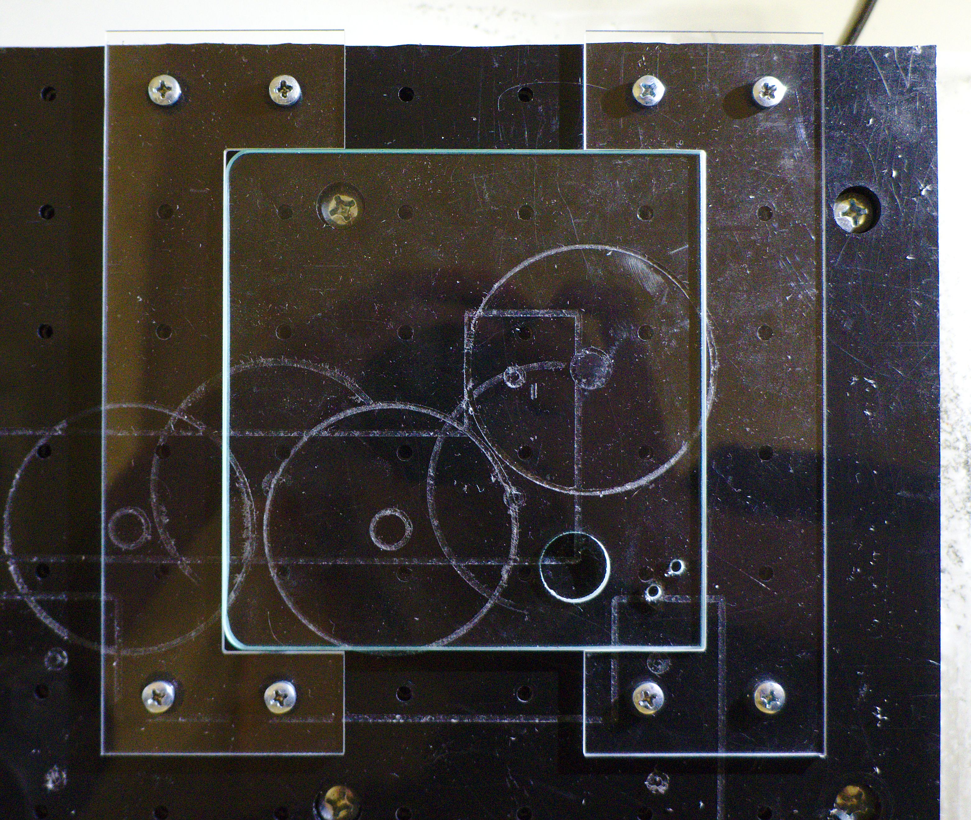
Note how the left part of the fixture has a gap to workpiece. This is because I in fact used it to determine the positioning error. The right part grips the glass tightly, so it is not a problem.
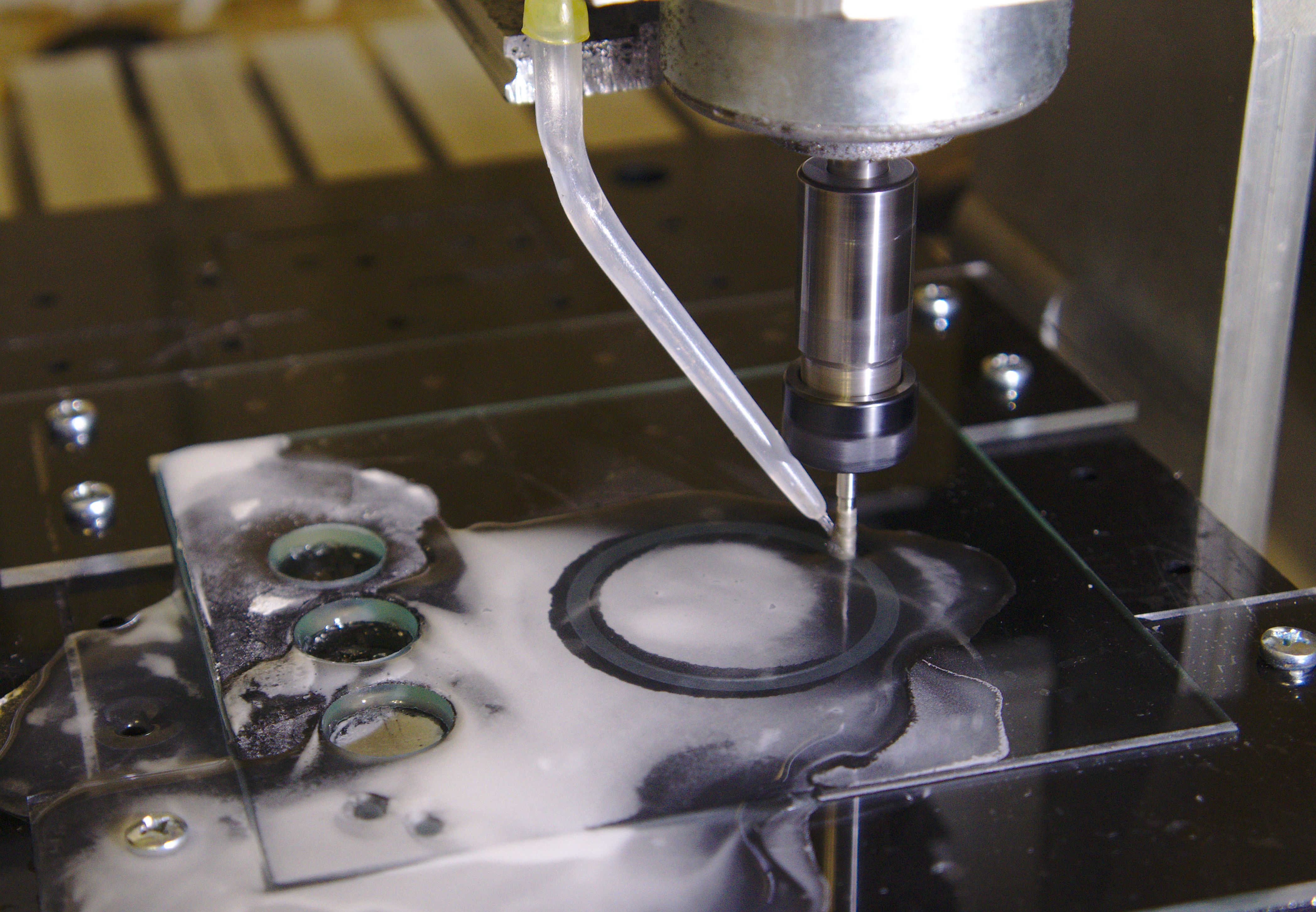
Milling glass
All parts of the flange are made using helical milling. This departs from the technique used for the acrylic flange, which plunged into the groove. The following is the adjusted parametric G-code:
1
2
3
4
5
6
7
8
9
10
11
12
13
14
15
16
17
18
19
20
21
22
23
24
25
26
27
28
29
30
31
32
33
34
35
36
37
38
39
40
41
42
43
44
45
46
47
48
49
50
51
52
53
54
55
56
57
58
59
60
61
62
63
64
65
66
67

( Helix-mill a hole. )
( Assumes metric, XY plane, feedrate, and tool compensation are set. )

O<helix_mill> sub
  #<xcenter> = #1 ( [mm] X center         )
  #<ycenter> = #2 ( [mm] Y center         )
  #<radius>  = #3 ( [mm] Hole radius      )
  #<zstart>  = #4 ( [mm] Z start position )
  #<zend>    = #5 ( [mm] Z end position   )

  G0 X[ #<xcenter> - #<radius> ] Y#<ycenter>

  G0 Z#<zstart>
  #<znow> = #<zstart>

  ( Mill out body with several full helical turns )
  O100 while [ #<znow> GT [ #<zend> + #<_zstep> ] ]

    #<znow> = [ #<znow> - #<_zstep> ]
    G2 I#<radius> J0 Z#<znow>

  O100 endwhile

  G2 I#<radius> J0 Z#<zend>

  ( Flat out the bottom )
  G2 I#<radius> J0

O<helix_mill> endsub

( --- BEGIN CONFIGURATION --- )

( 3.2mm diamond crown cutter )
T90 M6 S15000 F600

#<_zsafe>       = 10.  ( Safe Z               [mm] )
#<_zstep>       = 0.05 ( Pocketing Z step     [mm] )
#<_thickness>   = 3.9  ( Glass thickness      [mm] )

( --- END CONFIGURATION --- )

( Metric, Absolute, XY plane )
G21 G90 G17

( Spindle on, Coolant on )
M3 M8

( Dwell for 2s )
G4 P2

G0 Z#<_zsafe>
G0 X0 Y0

O<helix_mill> call [0.] [0.] [43. / 2] [0.] [-1.]
G0 Z#<_zsafe>

G41
O<helix_mill> call [0.] [0.] [8.0 / 2 - #5410] [0.] [-#<_thickness>]
G40
G0 Z#<_zsafe>

G42
O<helix_mill> call [0.] [0.] [60. / 2 + #5410] [-2.9] [-#<_thickness>]

G0 Z#<_zsafe>

M2
Cooling the tool with water is absolutely crucial. The Dremel bit comes with some proprietary mixture containing ethyleneglycol, but I have found that water also works. It might be worth investigating using antifreeze as coolant, though of course it is much more expensive than tap water.
I have tried a set of feeds, speeds and helical milling steps (which are just as essential as feeds/speeds for milling glass), and found that a wide range of settings work. In particular:
- Feed rate does not noticeably affect finish quality. (There will always be chipped edges; more on that later.) I have used feedrates from 10 to 600 mm/min at 4000 rpm with little difference.
- Spindle speed does not noticeably affect quality, but with a mill that uses PWM and a DC motor, low spindle speed will result in the tool seizing inside deep pockets. This does not seem to be due to direct friction, but rather, seemingly, due to water acting to prevent rotation instead of lubricating it. 4000 rpm was not enough, 15000 rpm was.
- Milling step does not noticeably affect quality, again. I did most of my testing with 50µm step to reduce the load on the tool and workpiece. With 600 mm/min feedrate, it is moderately quick.
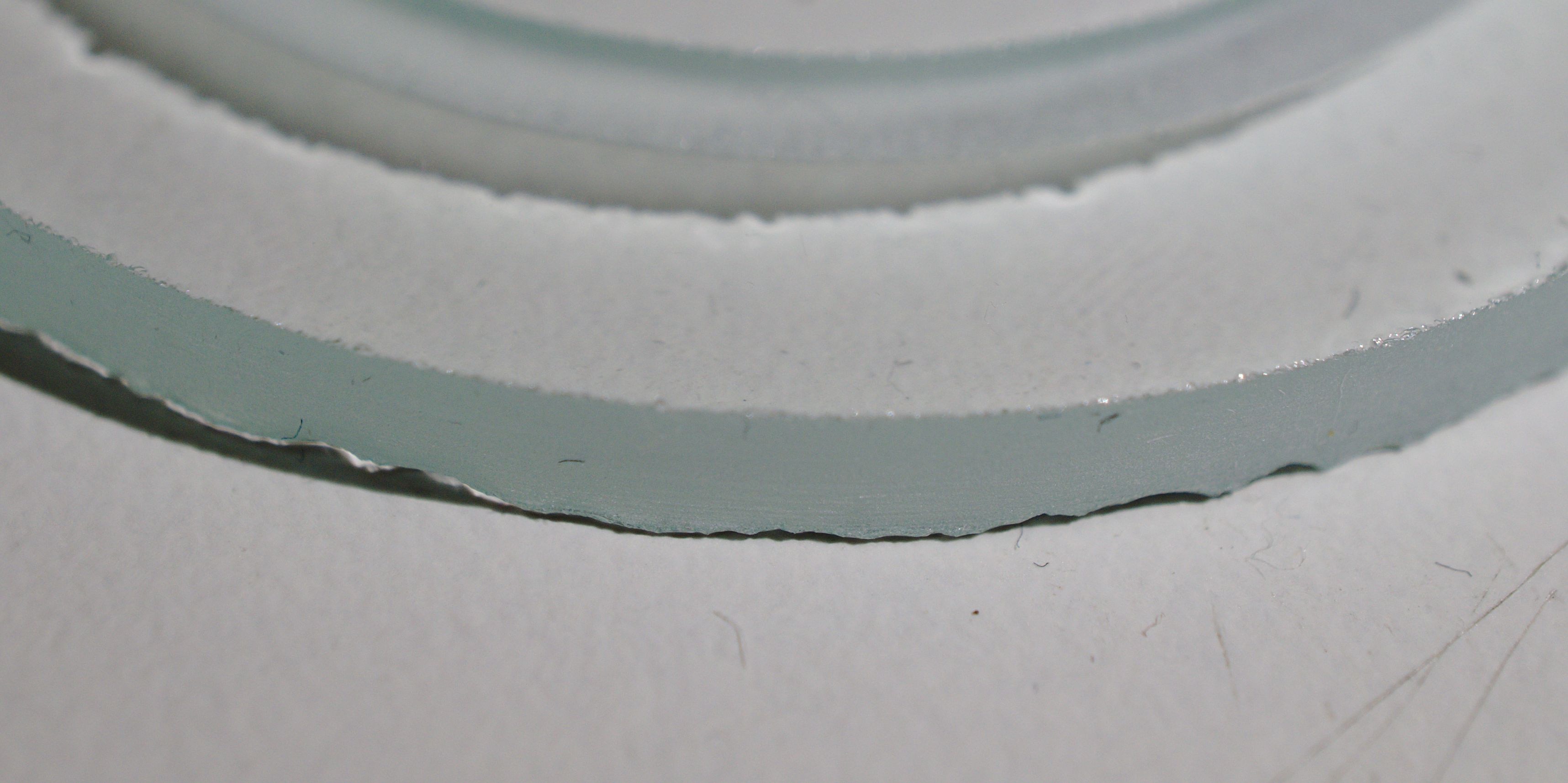
Unfortunately the workpiece seems to crack away when the pocket reaches the final ~0.4mm of glass, no matter how slow I go or how thin a step I use. I decided to just use a diamond file to dull the edge; the cracks don’t touch the bulk of material, so they don’t matter for my usage.
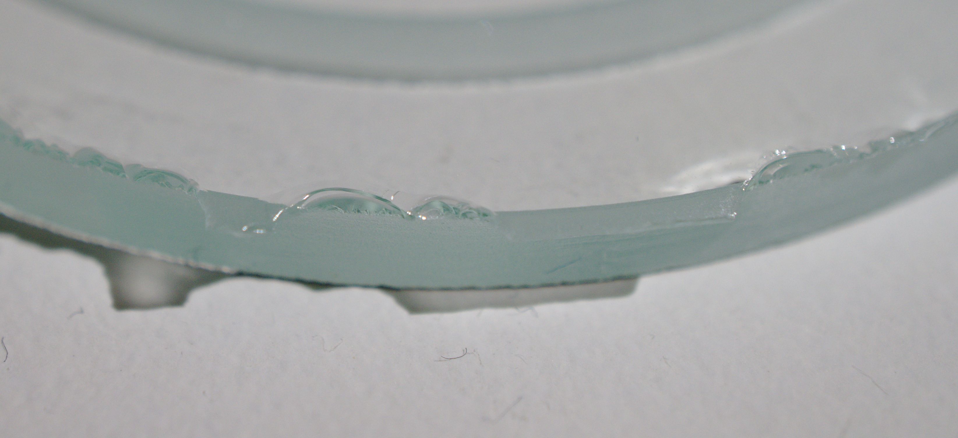
The top edges and inner edges (which are milled even after the non-fixed part of the workpiece breaks away) are chipped as well, though the defects are even smaller and duller.
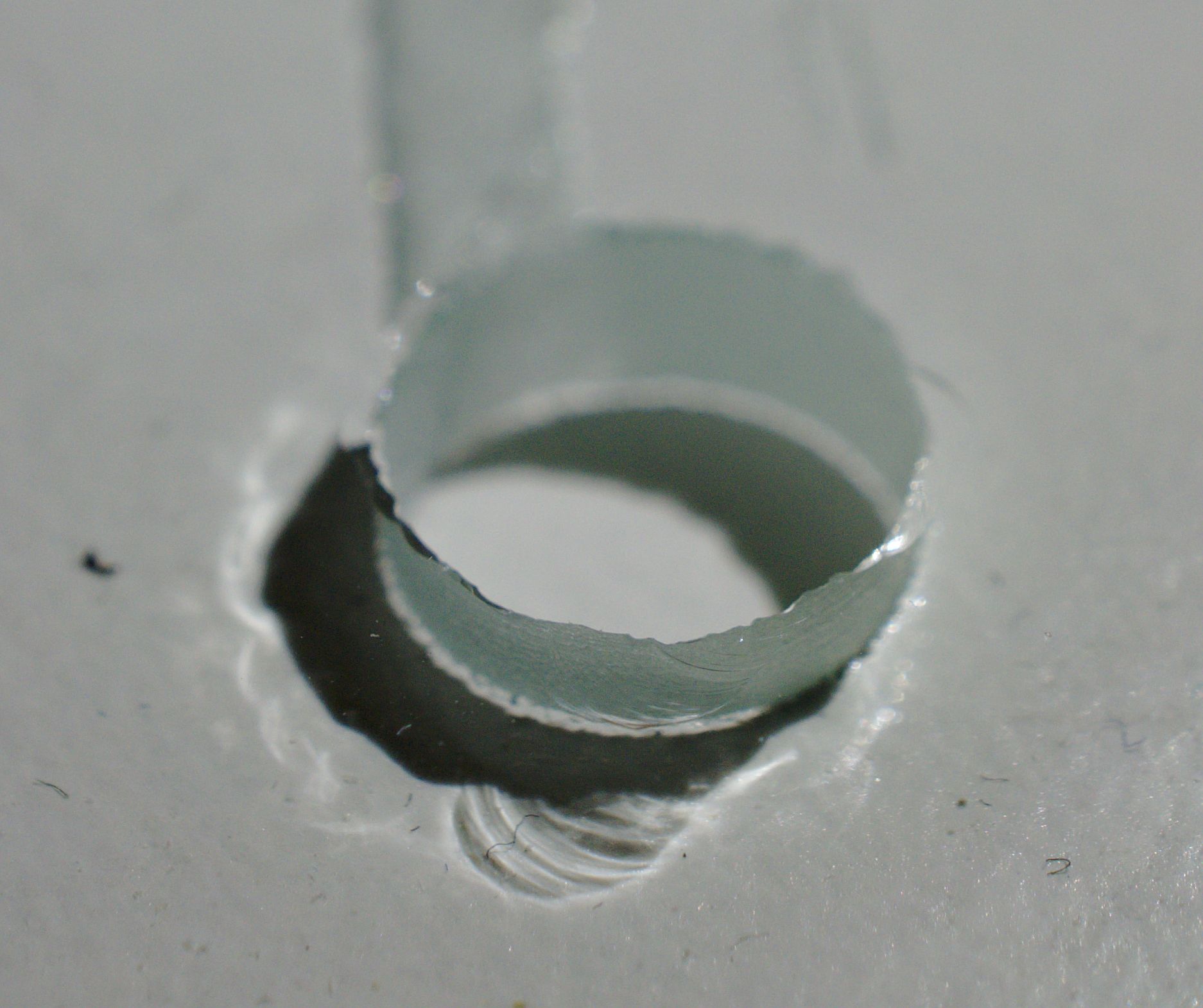
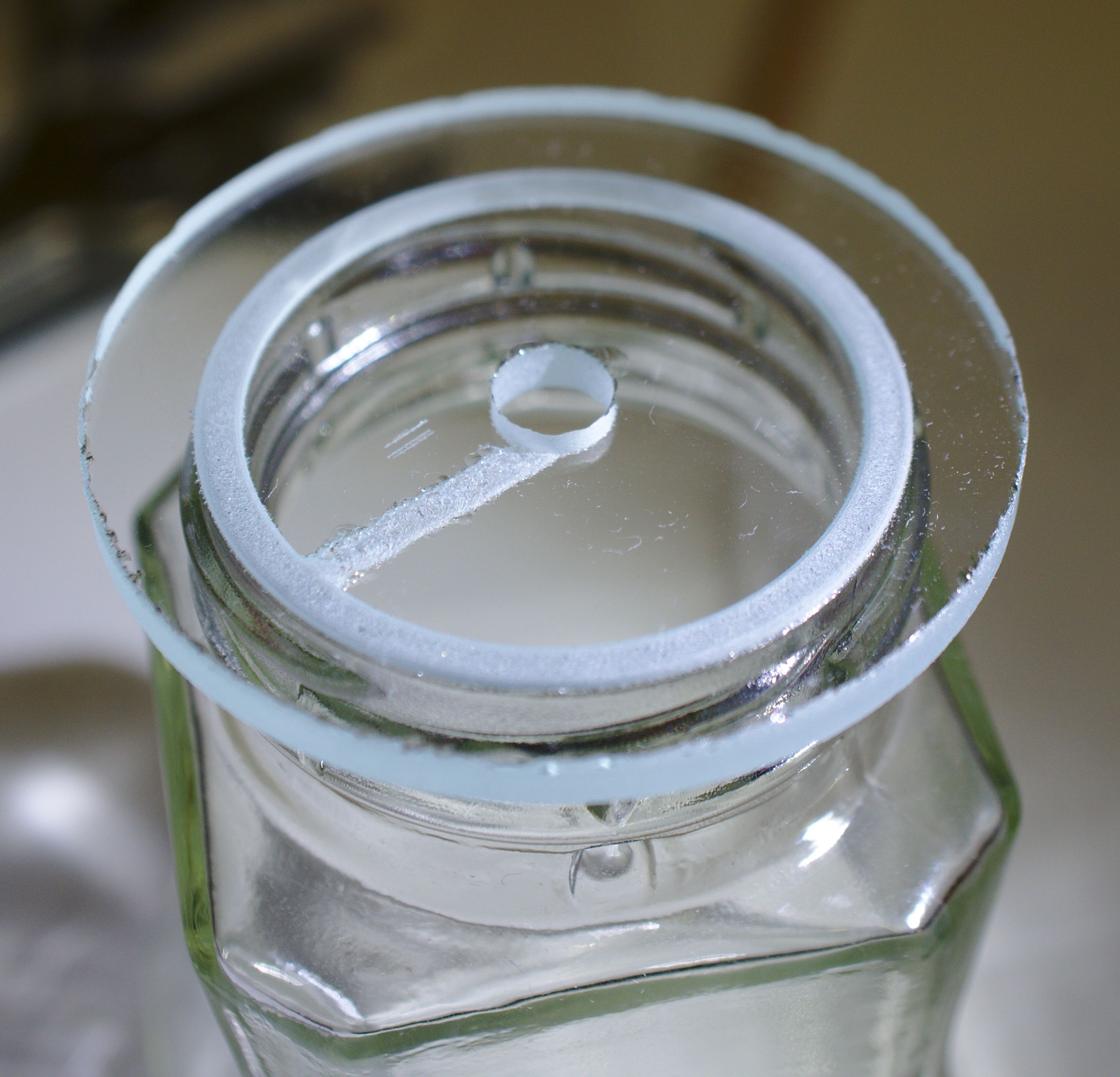
The straight path across the flange was a G-code bug, which is fixed in the G-code I publish.
Results
Working with glass is much easier than I expected. If minor chipping is not a problem for you, then it’s even easier than acrylic and aluminium.
It would be interested to mill an aspherical lens using this technique and a spherical diamond burr.
The new flange keeps the vacuum well. (Seal not pictured.)
The bathroom mirror shelves are a very good source of small, cheap glass panels. I can purchase them for about $0.40 each.