CNC3020T: poor positioning accuracy
Tags:The CNC3020T mill that I own has terrible repeat positioning accuracy. In this note I explore cause and possible solutions of this problem.
- Methodology
- Diagnostic/fix #1: capacitors
- Diagnostic #2: comparing channels
- Diagnostic #3: lowering acceleration
- Diagnostic #4: lowering maximum speed
- Diagnostic #5: swapping steppers
- Disassembling the spindle mount
- Fixing the actuators
Methodology
The problem is not readily apparent. I have noticed on multiple occasions that the X/Y movements can be not as precise as they’re claimed (vendor claims 50µm repeat positioning accuracy), and the Z position can be 0.3mm off, which looks benign, but can mean a difference between a clean cut and a broken tool for a 1mm endmill.
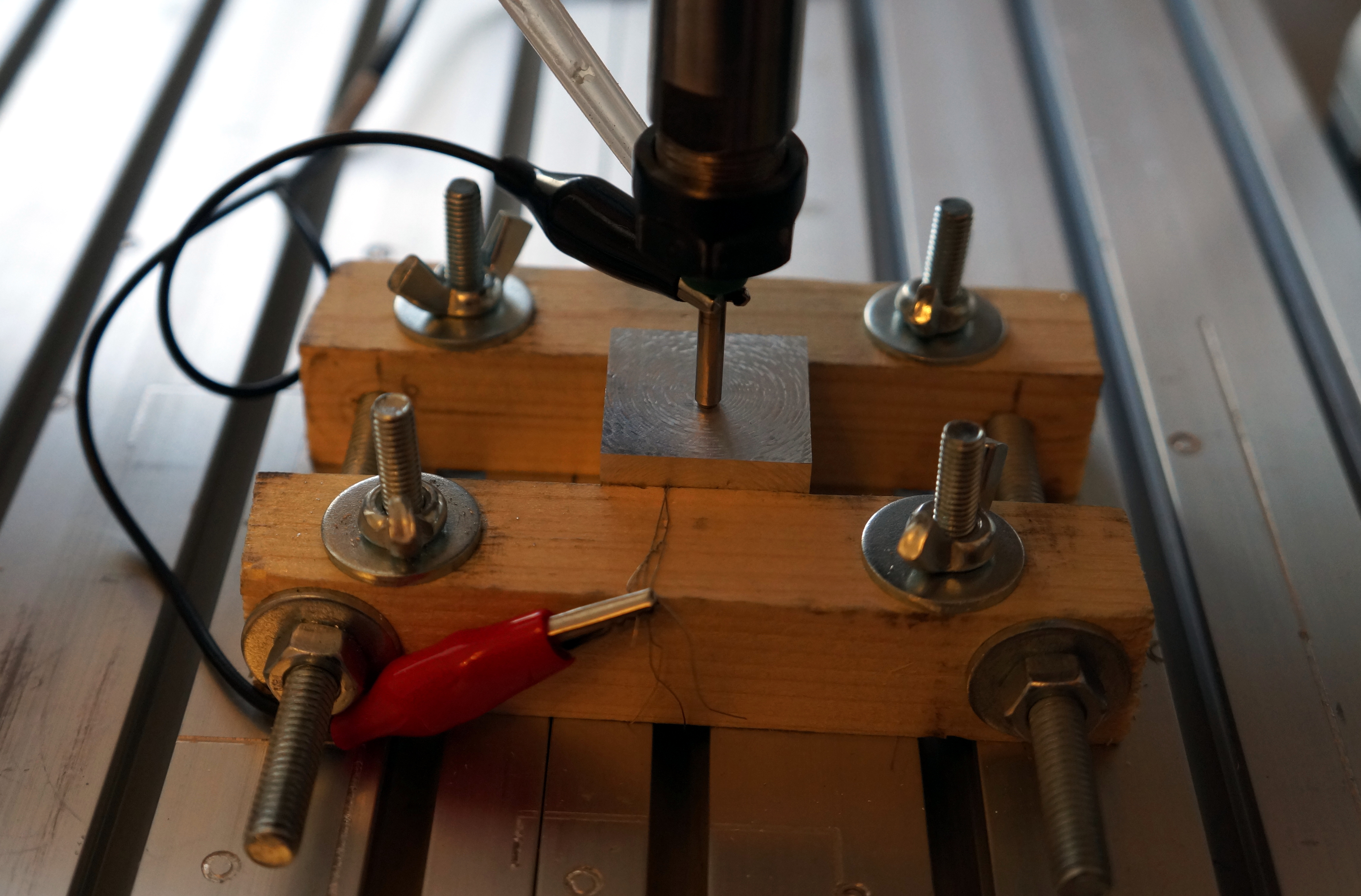
After setting up the probe, I acquired a simple way of testing the positioning accuracy. I would typically use a tool inserted the shank side down and position it to the right of a securely fixed piece of metal, then enter the following commands via MDI (the X axis is tested as an example):
1
2
3
4
5
6
7

G38.2 X-1
G10 L20 P0 X0 ; establish the origin point
G0 X100
X1
X100
X1 ; ... several times
G38.2 X-1
Then, the DRO will show the accumulated error.
The error is very bad for Z, but for X and Y it is quite a bit smaller; seems on the order of measurement precision.
Diagnostic/fix #1: capacitors
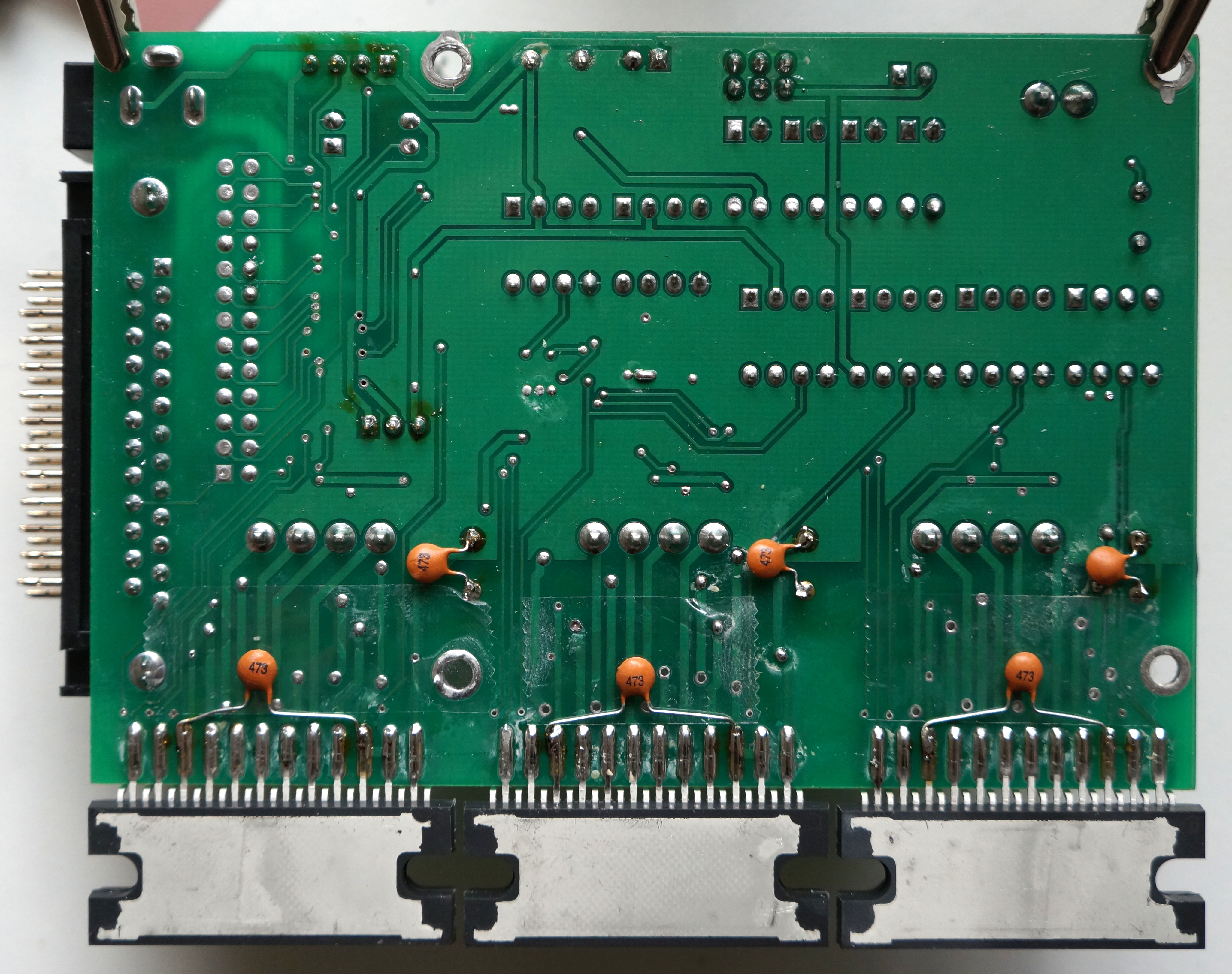
The control board lacks the necessary filtering capacitors on power rails, as noticed elsewhere on the net and by anyone who reads the TB6560 datasheet and compares it with control board layout.
I’ve soldered 470nF (based on the recommendation in the cnczone thread) capacitors on both the logic (pins 6 and 20 of TB6560) and power rails, but that appears to have had little effect. X/Y error may have improved, but only slightly (and they’re clearly within the spec now); the Z error remains.
Unfortunately I don’t have an oscilloscope right now, so it’s not possible to check for the noise on power rails.
Diagnostic #2: comparing channels
I’ve tried to swap the X and Z channels, using X as a known good, to see if the Z error will change. No change in error on either X or Z axis was observed; therefore, the problem is either mechanical or in configuration.
Diagnostic #3: lowering acceleration
Changing Z acceleration from 100mm/s² to 10mm/s² did not change the error. Indeed, the very first test accumulated 0.3mm of error over ~100mm of travel.
Diagnostic #4: lowering maximum speed
Changing Z maximum velocity from 11.7mm/s to 1.17mm/s did not change the error.
Diagnostic #5: swapping steppers
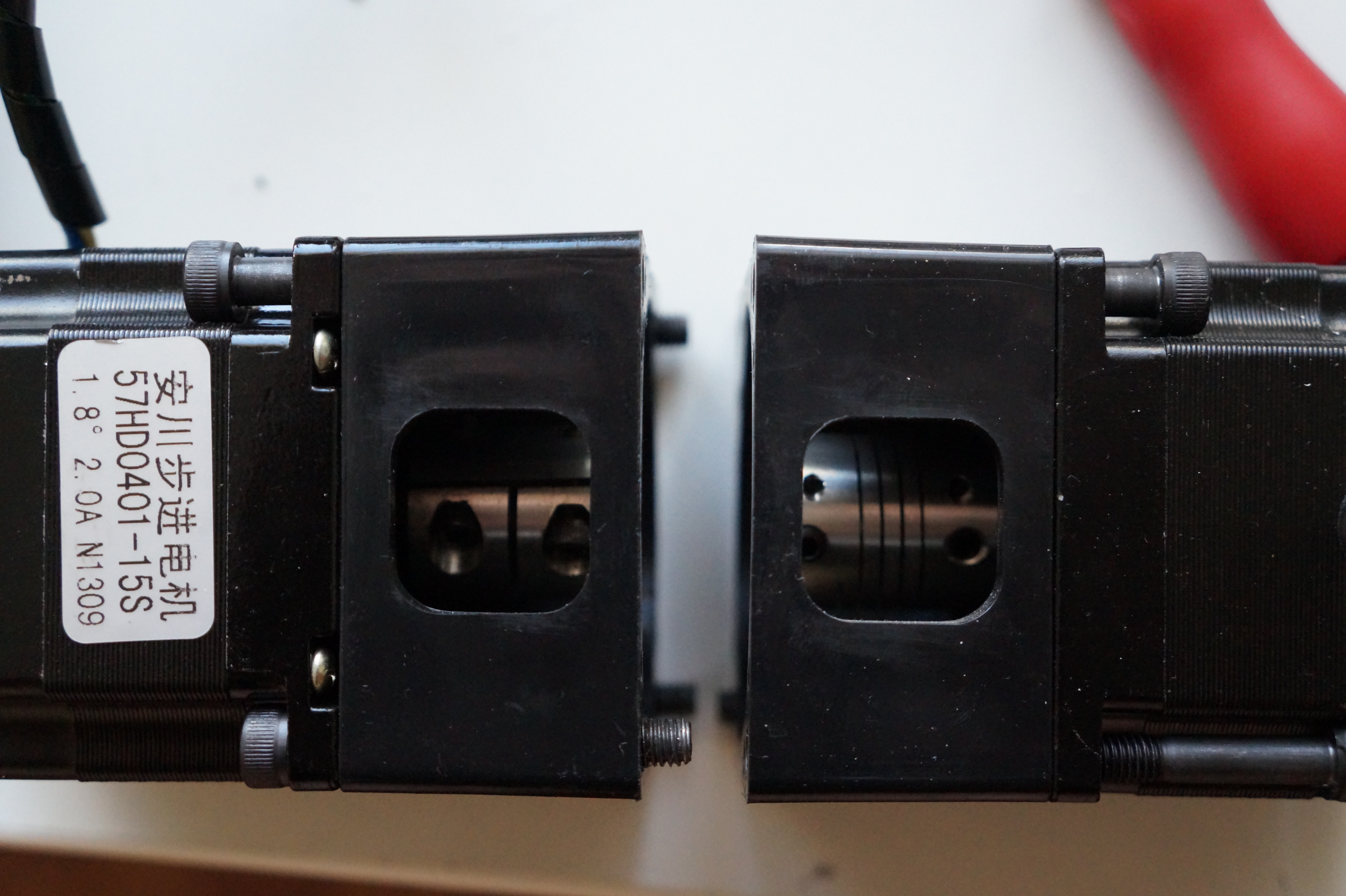
I’ve tried swapping X and Z steppers to determine whether they can be responsible for this. The steppers actually have different kind of motor shaft coupling as seen below. The Z type coupling (rigid) is on the left, X/Y type coupling (springed) is on the right:
After swapping, a glaring fault has become apparent: the ballnut assembly is completely broken. Rotating it either by hand or via the X/Y-type reveals that the spindle mount will “jump around”, seemingly skipping whole leadscrew threads. The fault has been masked all this time by the Z stepper mount, which actually put the entire weight of spindle on the Z stepper axle and its mount!
The leadscrew surface itself looks completely fine, and the “thread skipping” behavior is only seen to its full degree on the very top of the leadscrew, so the underlying reason is quite puzzling. I guess the problem is in the ballscrew assembly.
As a side note, I have discovered that the X channel is somehow faulty, as the motor connected to it heats up. Oddly, this doesn’t seem to affect the positioning.
Disassembling the spindle mount
So to fix the problem, I started taking it apart. Cue several interesting discoveries.
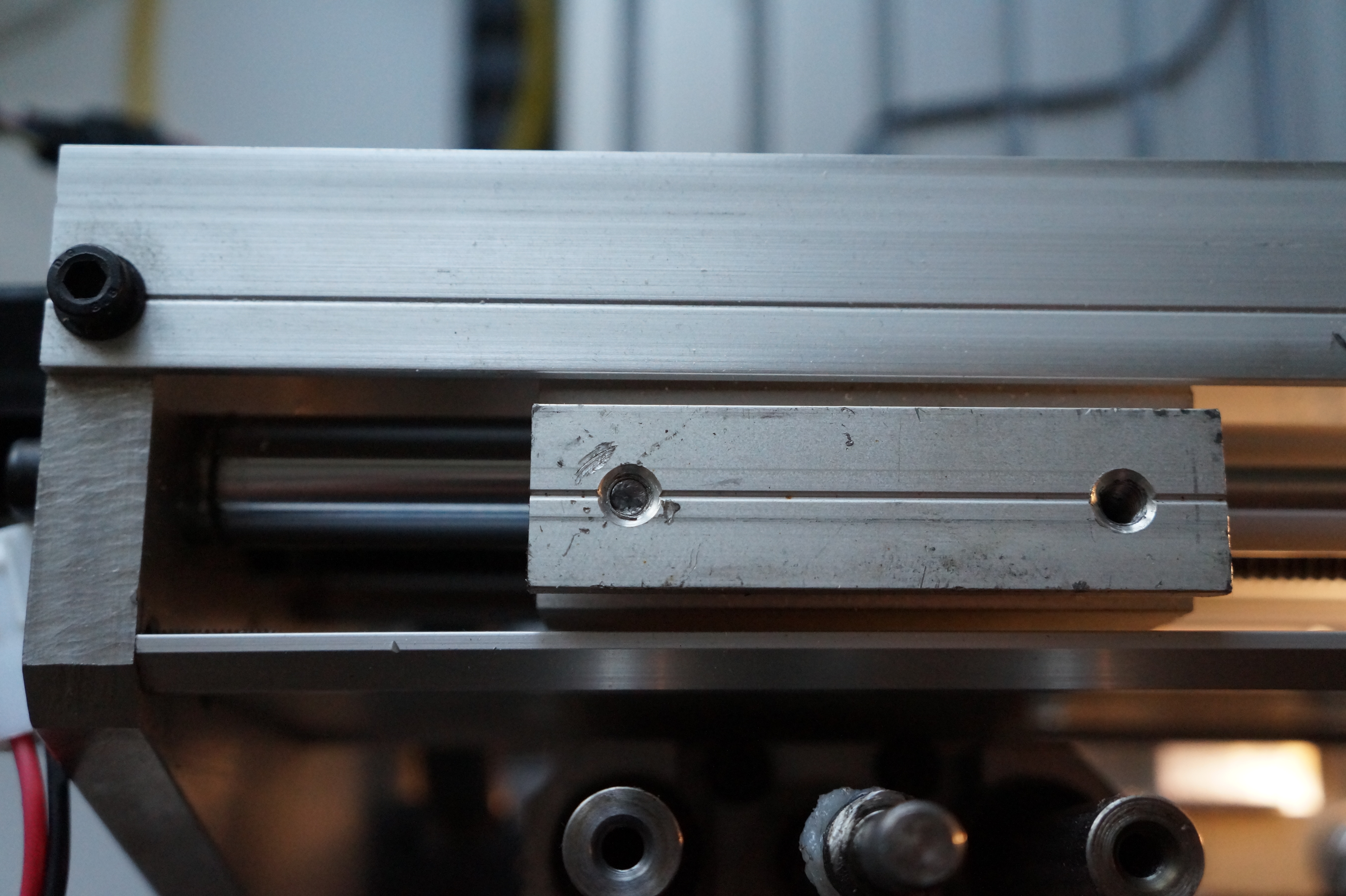
First, the Chinese assembly people have accidentally sheared a screw, left half of it inside the X caret, drilled out the other half, tapped an M6 thread in its place and screwed a slightly bigger bolt inside to hide their mistake. What the fuck :(


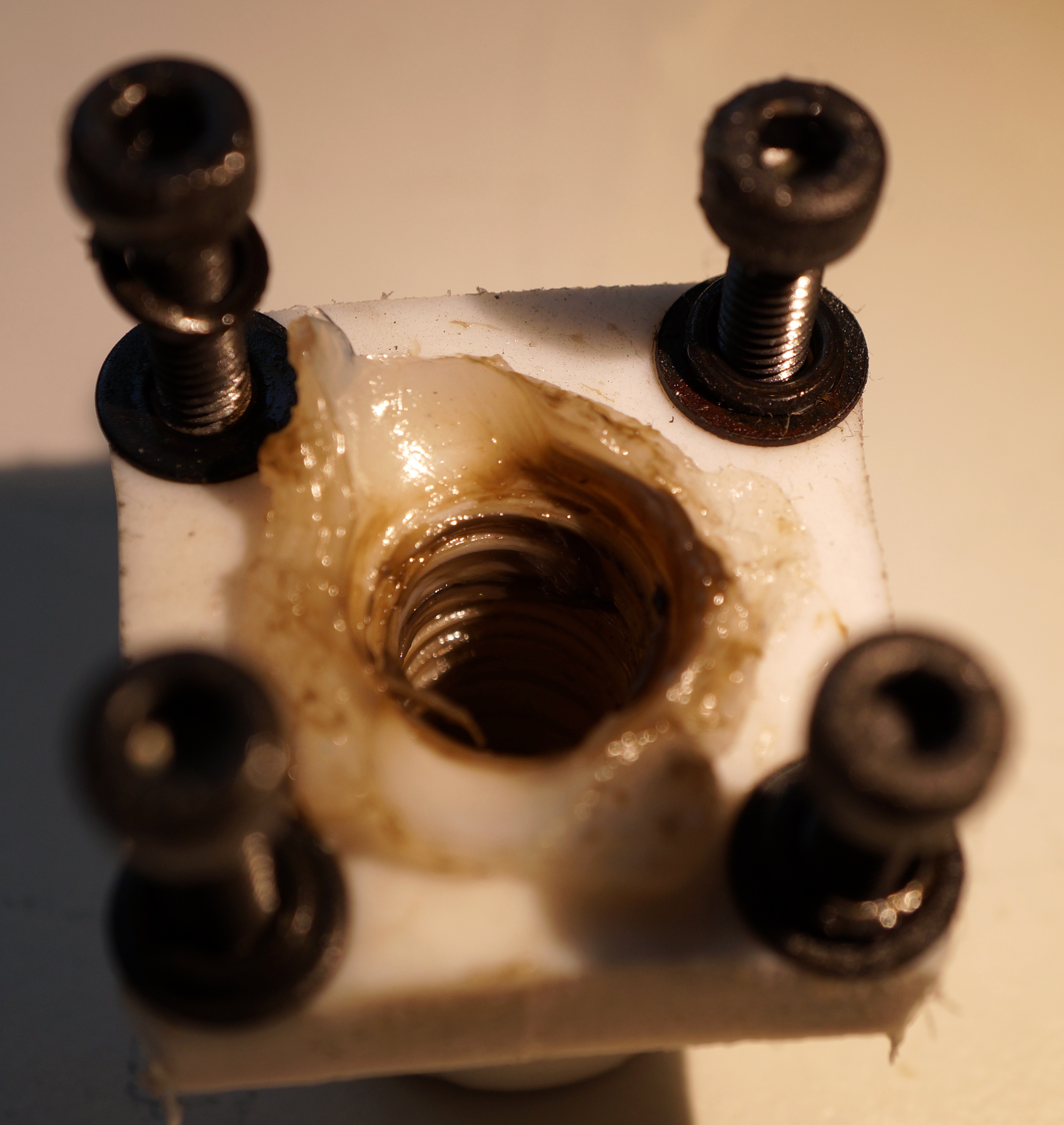
Second, the actuator does not actually have a ballnut assembly. It just has a piece of threaded PTFE!
Third, apparently they also have forgot to lubricate the linear ball bearings; there is both no apparent lubricant and after wiping the rails with a tissue, the only thing that’s left is the rails metal, ground to fine powder. As a result, the balls made a set of grooves in the guiding rails. No wonder there is no precision! I do not yet know if a recovery is possible; perhaps rails could be rotated by 45° to make balls slide over flat surface again. Not sure whether the balls are deformed beyond acceptable bounds.

Fixing the actuators
I have decided to repair the linear actuator assembly. Since there are only four grooves on the rails, 90° apart, it’s possible to get back to the smooth surface by rotating them, e.g. by 45°. And, if the bearings themselves are intact, then after lubricating them the assembly should start working properly again.
First, I have disassembled the whole spindle mount and cleaned all lubricant residue, both on linear bearings and PTFE nut. The PTFE nut was easy to clean; for ball bearings, I have thoroughly rinsed them using a dimethoxymethane aerosol while rotating the balls around. The aerosol has carried away a lot of particles, seemingly coming from the surface of the rails, ground to very fine dust.
Then, I have re-lubricated the assembly. For the PTFE nut I used a PTFE-based grease, and I have applied a large amount of PTFE-based oil lubricant to the ball bearings, while rotating the balls around several dozen times.
After re-lubricating, I have tried moving the bearings over the rails by hand. Surprisingly, there was not much change; the bearings still were very “jumpy” and not smooth at all. Considering that there is definitely no way of replacing them, and the whole spindle mount is custom-made CNC-machined aluminium extrusion, I have decided to assemble it back. Even more surprisingly, it appears that my fix has worked; the movement is now quite smooth, despite the fact that the Z leadscrew requires 1.5-2x more force to rotate (measured by hand).
The testing has demonstrated that the Z axis is now precise within 10µm after 10cm of travel. Awesome!